Slipper type 3D printer with parallel connecting rods and movable platform

A 3D printer, slider-type technology, applied in processing platforms/substrates, 3D object support structures, additive manufacturing, etc., can solve problems affecting printing quality, wire drawing, and high surface roughness of printed parts, avoiding printing failures, reducing The effect of drawing phenomenon and improving printing accuracy

Active Publication Date: 2018-07-17
JILIN UNIV
View PDF11 Cites 3 Cited by
  • Summary
  • Abstract
  • Description
  • Claims
  • Application Information

AI Technical Summary

Problems solved by technology

However, this method is limited by the speed of the extrusion head and the moving speed of the nozzle, and the phenomenon of wire drawing often occurs, resulting in a higher surface roughness of the printed part, which affects the printing quality.
This limits the development of 3D printing technology printing quality

Method used


Image

  • Slipper type 3D printer with parallel connecting rods and movable platform
  • Slipper type 3D printer with parallel connecting rods and movable platform
  • Slipper type 3D printer with parallel connecting rods and movable platform

Examples


Embodiment 1

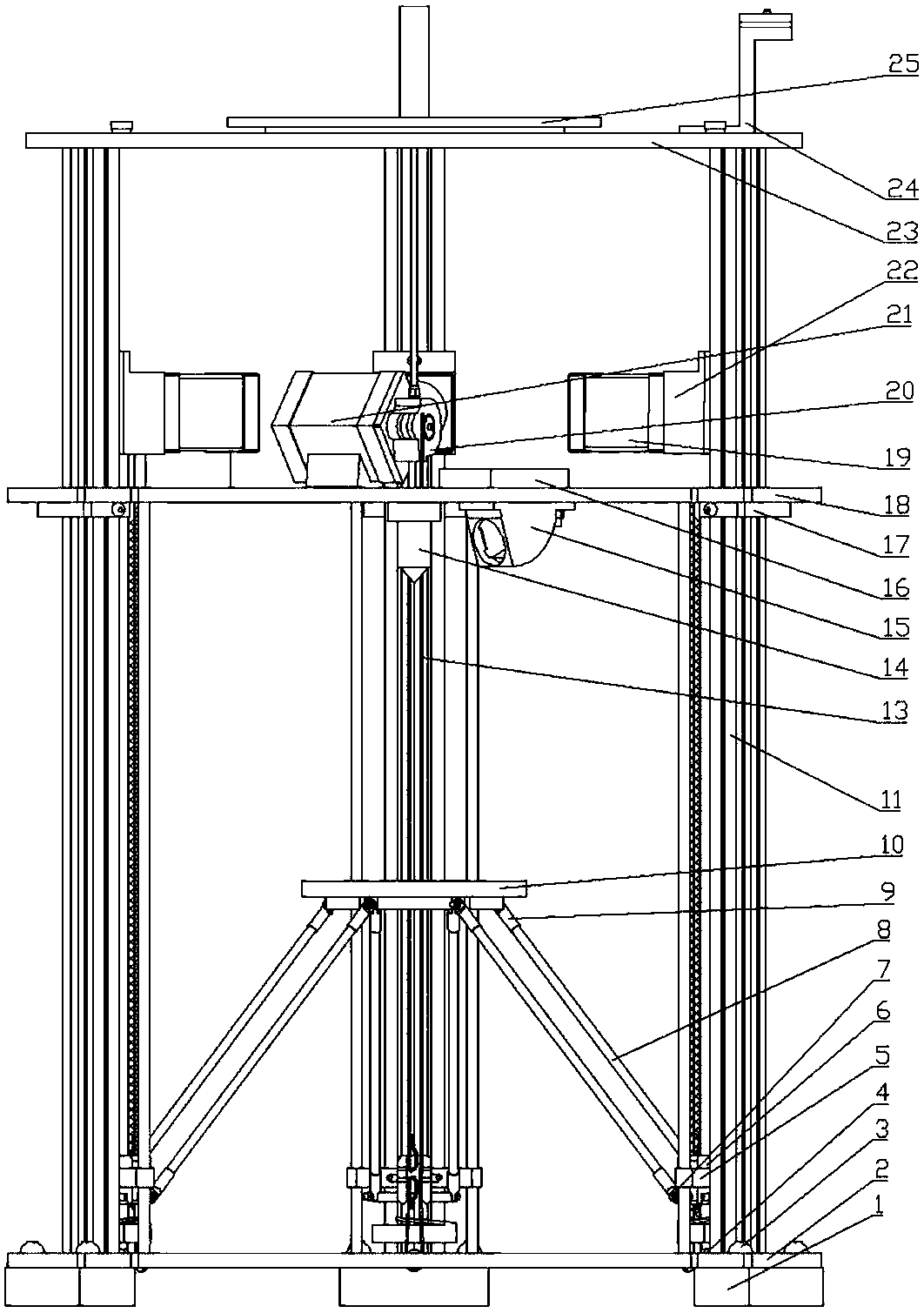
[0028] Such as figure 1 and figure 2 As shown, in this embodiment, a movable 3D printer with a parallel-link slider type platform is mainly composed of a double-layer cylindrical frame, a nozzle 14, a platform movement mechanism and a printing platform 10;

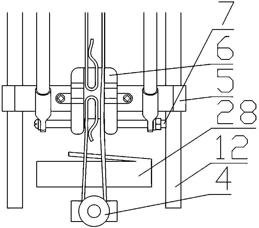
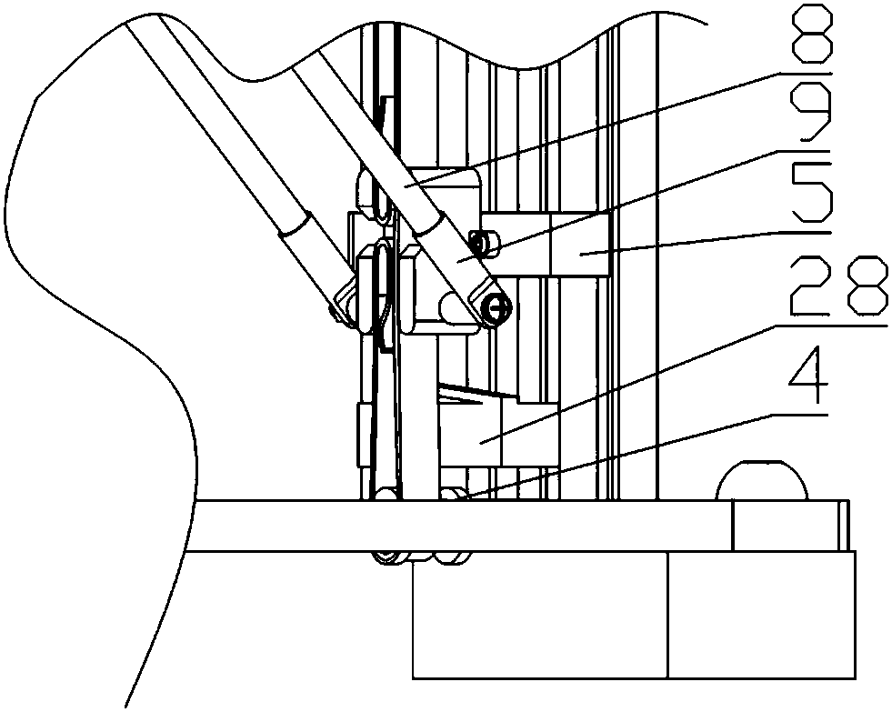
[0029] The frame is mainly composed of a base plate 2, a bracket 11, a nozzle support plate 18 and a top plate 23; wherein, the base plate 2 is located at the bottom of the frame, and three bases 1 are installed at the bottom of the base plate 2 as supports; there are six brackets 11, each Two groups are divided into three groups, evenly arranged on the base plate 2, and the lower end of the bracket 11 is inserted into the preset slot on the base plate 2, the middle part of the bracket 11 passes through the slot on the nozzle support plate 18, and the nozzle support plate 18 passes through it. The nozzle support plate fixing seat 17 fixedly installed below limits it on the bracket 11, and the upper part of the bracket 11...


PUM


Abstract

The invention discloses a slipper type 3D printer with parallel connecting rods and a movable platform, and belongs to the technical field of digital machining. The invention aims to solve the problems that a current 3D printer adopts a fixed platform, and a printing heat is driven by a stepping motor to move; this way is restricted by the wire speed of an extrusion head and the movement speed ofthe printing head, and accordingly wiredrawing phenomena frequently occur, resulting in high partial surface roughness of printed parts and influence on the printing quality. A printing platform is driven to move by the stepping motor through three groups of parallel connecting rods, and meanwhile the printing head is fixed; and the above problems are avoided, and the problem of the printing quality due to wiredrawing is solved.

Description

technical field [0001] The invention belongs to the technical field of digital processing. Background technique [0002] 3D printing is a production and processing technology based on digital models. Firstly, the computer slices the digital model to generate corresponding codes, and uses fused deposition technology, selective laser sintering technology or light curing technology to print layer by layer. The production and processing of objects. [0003] Currently, the common printing arrangement of existing 3D printers is that the working platform does not move, and the printing nozzle moves through the stepping motor control, and at the same time, the nozzle extrudes printing consumables, and the consumables are superimposed on the stationary part that has been printed to form an entity. However, this method is limited by the speed of the extrusion head and the moving speed of the nozzle, and the phenomenon of stringing often occurs, resulting in a higher surface roughness...

Claims


Application Information

Patent Timeline
Patent Type & Authority Applications(China)
IPC IPC(8): B29C64/118B29C64/245B29C64/232B29C64/236B29C64/393B33Y30/00B33Y50/02
CPCB33Y30/00B33Y50/02
Inventor 王学旭曲兴田孙慧超闫龙威张昆郭思廷王宏一
Owner JILIN UNIV
Why Eureka
Try Eureka