Automatic exhaust device for transformer gas relay

An automatic exhaust, relay technology, applied in electrical components, circuits, electrical switches, etc., can solve problems such as low efficiency, transformer misdetection, shaking, etc., to achieve the effect of saving labor

Active Publication Date: 2018-07-17
宁波隆锐机械制造有限公司
View PDF6 Cites 4 Cited by
  • Summary
  • Abstract
  • Description
  • Claims
  • Application Information

AI Technical Summary

Problems solved by technology

[0006] 1. When the transformer is working normally, it often produces vibrations, such as the vibration of the iron core caused by magnetostriction, the vibration of the iron core caused by the magnetic flux leakage between the joints of the silicon steel sheets and the laminations; under the normal operating voltage of the relay, due to The action of the alternating magnetic field, inappropriate stop position, contact between the tongue and the magnetic pole, and insufficient elasticity of the static contact piece will also be in a state of vibration. Therefore, the light-shielding float in the above-mentioned patent solution will shake on the oil surface due to vibration. , so that the photosensitive probe can also receive the laser light from the laser without generating gas, which will easily cause a false detection of whether the transformer is faulty
[0007] 2. After the gas relay is deflated, part of the oil will be consumed after the oil decomposes the gas, so it is necessary to refuel the relay. The existing refueling work is generally done manually, which is inefficient

Method used


Image

  • Automatic exhaust device for transformer gas relay
  • Automatic exhaust device for transformer gas relay

Examples


Embodiment Construction

[0036] Further detailed explanation through specific implementation mode below:

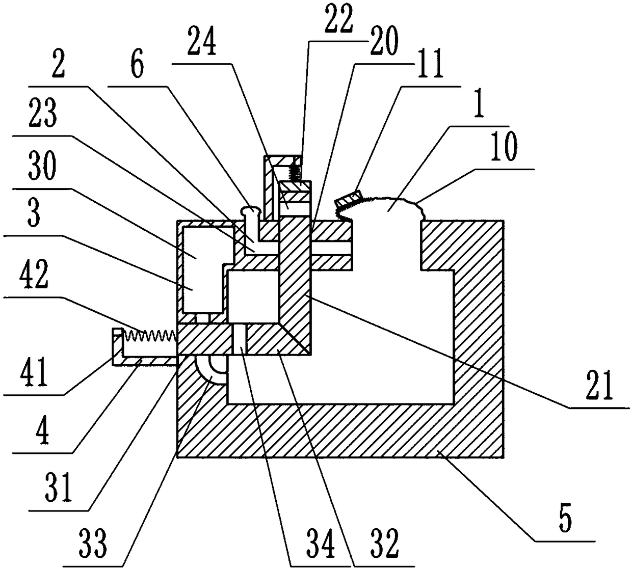
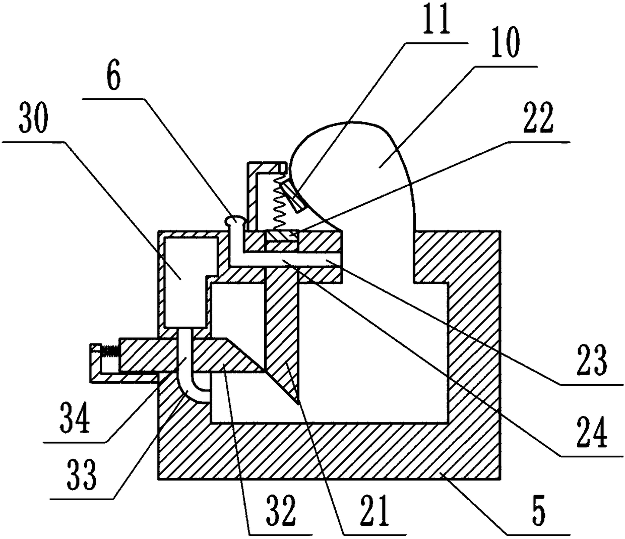
[0037] The reference signs in the drawings of the description include: gas collection mechanism 1, special-shaped airbag 10, magnet 11, exhaust mechanism 2, first through hole 20, first slider 21, magnet block 22, exhaust pipe 23, connecting hole 24. Oil supply mechanism 3, oil storage chamber 30, second through hole 31, second slider 32, oil supply pipeline 33, connection hole 34, reset mechanism 4, fixed frame 41, torsion spring 42, gas relay 5, Gas collection device 6.

[0038] Such as figure 1 and figure 2 As shown, the automatic exhaust device of transformer gas relay 5 of the present invention includes:

[0039] Gas collection mechanism 1, such as figure 1 As shown, an opening is provided at the upper end of the gas relay 5 biased to the right, and the opening on the top of the gas relay 5 is connected with a special-shaped air bag 10 by glue, and the special-shaped air bag 10 communic...


PUM


Abstract

The invention discloses an automatic exhaust device for a transformer gas relay, and relates to the field of transformer maintenance auxiliary equipment. After gas appears inside the gas relay and anirregularly-shaped air bag is filled with gas, the irregularly-shaped air bag is expanded, a first sliding block is pushed to move downwards through the repulsive force of a magnet and a magnet blockwith same polarity, and then a second sliding block is pushed to move outwards through the wedge-shaped cooperation of the contact end face of the first sliding block and the second sliding block, sothat a broken exhaust pipeline and an oil supply pipeline are opened, automatic exhaust and oil supply are realized, and then the normal positions of the first sliding block and the second sliding block are recovered to close the exhaust pipeline and the oil supply pipeline by using the combined action of the reduction of the repulsive force of the shrunk magnet and the magnet block of the irregularly-shaped air bag in the gradual gas exhaust process. The device solves the problems that an existing gas relay exhaust device is easy to misdetect whether a fault appears in a transformer and oil cannot be supplied automatically, and is mainly used for automatically exhausting gas and supplementing transformer oil consumed inside the gas relay.

Description

technical field [0001] The invention relates to the field of transformer maintenance auxiliary equipment, in particular to an automatic exhaust device for a transformer gas relay. Background technique [0002] Gas relay (also known as gas relay) is a protective device used in transformers. It is installed in the pipeline between the oil conservator and the oil tank of the transformer. The insulating material decomposes, thereby producing a large amount of flammable gas, which is collectively referred to as gas gas. Among them, the light gas is mainly reflected when the transformer has a slight fault, and the gas decomposed from the oil rises into the gas relay. Staff need to deflate. [0003] The deflation work of the traditional gas relay needs to be done manually. When there is gas or a fault in the main transformer, it is necessary to send a person or a special car to the site to deflate the gas in time. The inability to deflate in time has seriously affected the safe ...

Claims


Application Information

Patent Timeline
Patent Type & Authority Applications(China)
IPC IPC(8): H01H35/26
CPCH01H35/26
Inventor 项文增
Owner 宁波隆锐机械制造有限公司
Why Eureka
Try Eureka