Ball head milling cutter for high-temperature alloy milling

A ball-end milling cutter and superalloy technology, which is applied in the field of machining, can solve the problems affecting the workpiece surface quality, tool life, machining accuracy and machining surface quality inconsistency, cutting edge and flank wear, etc. Better surface quality, higher surface residual height value, lower cutting force effect

Inactive Publication Date: 2018-07-20
HARBIN UNIV OF SCI & TECH
View PDF6 Cites 0 Cited by
  • Summary
  • Abstract
  • Description
  • Claims
  • Application Information

AI Technical Summary

Problems solved by technology

[0002] Superalloys have good properties such as thermal fatigue, thermal stability, and thermal strength. They can withstand complex stress and work normally in high-temperature environments. They are widely used in the aviation manufacturing industry. Difficult processing of superalloy materials is a difficult point in the current manufacturing industry. Cutting In the process, there are problems such as high cutting temperature, high cutting force, serious tool wear, machining accuracy and machined surface quality that do not meet the requirements. The flank of the traditional blade type ball end milling cutter is a continuous plane. The surface friction of the workpiece is large, and a large amount of cutting heat is generated in the contact area between the cutting edge and the flank face and the workpiece, and it is difficult to spread. Under the action of high temperature and high pressure, the cutting edge and the flank face are severely worn, which directly affects the surface quality of the workpiece and the service life of the tool.

Method used


Image

  • Ball head milling cutter for high-temperature alloy milling
  • Ball head milling cutter for high-temperature alloy milling
  • Ball head milling cutter for high-temperature alloy milling

Examples


Embodiment Construction

[0018] In order to make the technical problems, technical solutions and advantages to be solved by the present invention clearer, the following will describe in detail with reference to the drawings and specific embodiments.

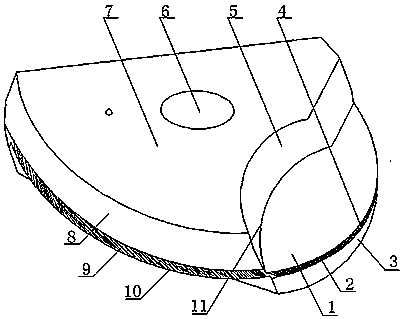
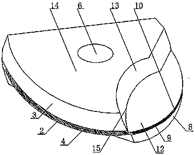
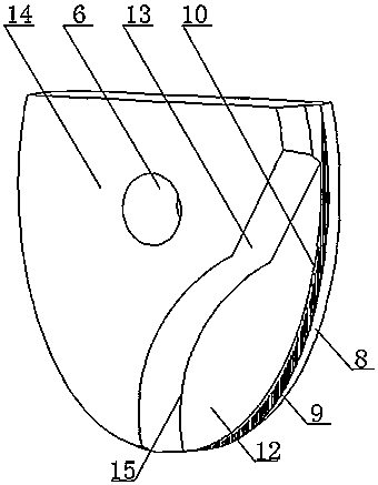
[0019] see Figure 1-4 , the present invention provides a technical solution: a ball end milling cutter for high-temperature alloy milling, which includes a cutter head composed of cutting edge one (4) and cutting edge two (10), and front Face one (1), first flank (2), second flank (3), rake face two (12), first flank (9), second flank (8) , the first flank (2) and the first flank (9) are surfaces provided with an oblique texture structure (17), and the rake surface one (1) and the first groove surface (5) constitute the first hook Describe the chip flute (11), the second rake face (12) and the second groove surface (13) constitute the second hook-shaped chip flute (15), the upper surface (7) and the lower surface (14) of the cutter head Fastening scre...


PUM


Abstract

The invention discloses a ball head milling cutter for high-temperature alloy milling. The ball head milling cutter for high-temperature alloy milling comprises a tool bit comprising a first cutting edge and a second cutting edge, and further comprises a front tool face, a first rear tool face and a second rear tool face which are connected with the cutting edges; the first rear tool face is a surface with an inclined grain structure; and a hook-shaped chip containing groove is formed by the front tool face and a groove face. The problem that high-temperature alloy materials are difficult to machine is the difficult point in the current manufacturing industry, the problems that the cutting temperature is high, cutting force is large, abrasion of a tool is severe, and the machining precision and the machining surface quality do not meet the requirements exist in the cutting process, and through a series of innovative design, the ball head milling cutter for high-temperature alloy milling has the advantages of reducing the cutting temperature and cutting force, resisting abrasion, improving the machining surface quality, prolonging the service life of the tool and being good in cutting performance.

Description

technical field [0001] The invention relates to a cutting tool in the field of mechanical processing, in particular to a blade-type special milling cutter for high-temperature alloy milling. Background technique [0002] Superalloys have good properties such as thermal fatigue, thermal stability, and thermal strength. They can withstand complex stress and work normally in high-temperature environments. They are widely used in the aviation manufacturing industry. Difficult processing of superalloy materials is a difficult point in the current manufacturing industry. Cutting In the process, there are problems such as high cutting temperature, high cutting force, serious tool wear, machining accuracy and surface quality that do not meet the requirements. The flank of the traditional blade type ball end milling cutter is a continuous plane. The surface friction of the workpiece is large, and a large amount of cutting heat is generated in the contact area between the cutting edge...

Claims


Application Information

Patent Timeline
Patent Type & Authority Applications(China)
IPC IPC(8): B23C5/02B23C5/28
CPCB23C5/02B23C5/28
Inventor 刘献礼牛壮施金奎赵泽民范梦超
Owner HARBIN UNIV OF SCI & TECH
Why Eureka
Try Eureka