Thermal power plant thermoelectric decoupling system

A technology for thermal power plants and heating systems, applied in the field of thermal power plants, can solve problems such as the great influence of the return water temperature of the heating network, the limited capacity of thermoelectric decoupling, and the decline in the extraction capacity of the middle exhaust, so as to achieve technical transformation with little difficulty and risk , The effect of short technical transformation cycle and small modification

Inactive Publication Date: 2018-07-20
UNI RISING BEIJING TECH CO LTD
View PDF4 Cites 15 Cited by
  • Summary
  • Abstract
  • Description
  • Claims
  • Application Information

AI Technical Summary

Problems solved by technology

First, the middle row (conventional) steam extraction heating technology, which is the foundation of "thermoelectric coupling", without the ability of "thermoelectric decoupling"
Second, the optical axis heating technology, on the surface, is equivalent to "getting rid of" the low-pressure cylinder of the steam turbine. However, for a power plant with a dual-unit configuration, only "one optical axis unit" can be used, and the other must maintain "steam extraction and supply". hot mode
In this way, the ability of "thermoelectric decoupling" is largely limited
Third, the double back pressure and double rotor heating technology of the water cooling unit is greatly affected by the return water temperature of the heating network
For the severe cold period, the return water temperature of the heating network is high, and this solution will have some fatal problems: 1. The increase of back pressure will lead to the decline of the steam

Method used


Image

  • Thermal power plant thermoelectric decoupling system
  • Thermal power plant thermoelectric decoupling system
  • Thermal power plant thermoelectric decoupling system

Examples


Embodiment 1

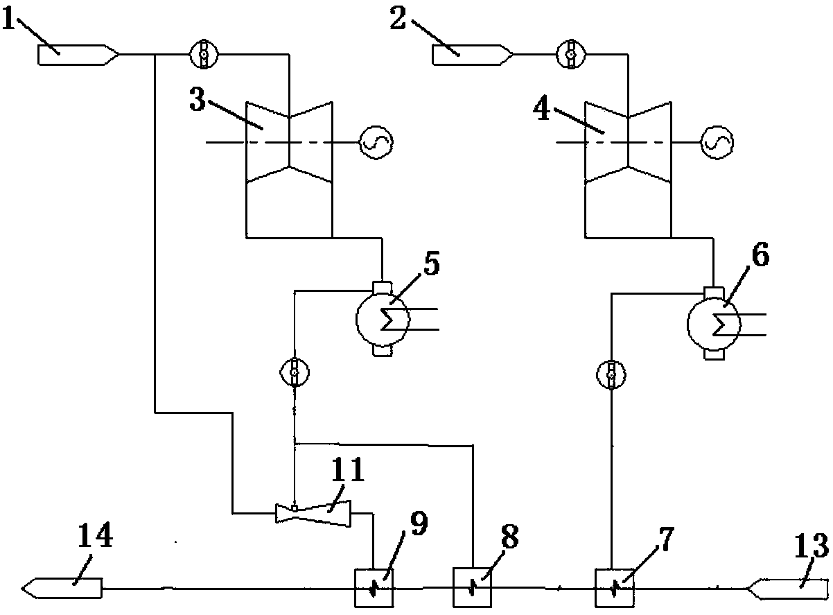
[0031] Such as figure 1 As shown, a power plant is installed with two 300MW units, and the exhaust steam of the two steam turbines is recycled at the same time. The two steam turbines have different operating back pressures, which are the high back pressure steam turbine 3 and the low back pressure steam turbine 4 respectively. For example, two 300MW steam turbine units (direct air-cooled, indirect air-cooled, water-cooled can be used), and two 300MW units run at the same time. During winter operation, one of the steam turbines operates at a back pressure of 15KPa, the other operates at a back pressure of 18KPa, and the return water of the heating network is 15,000t / h. (15KPa and 18KPa and 15000t / h are just examples for convenience of description. Configuration methods of other parameters are also within the protection scope of the present application). The exhaust steam of both units is recycled.

[0032] Thermoelectric decoupling system of thermal power plant, including t...

Embodiment 2

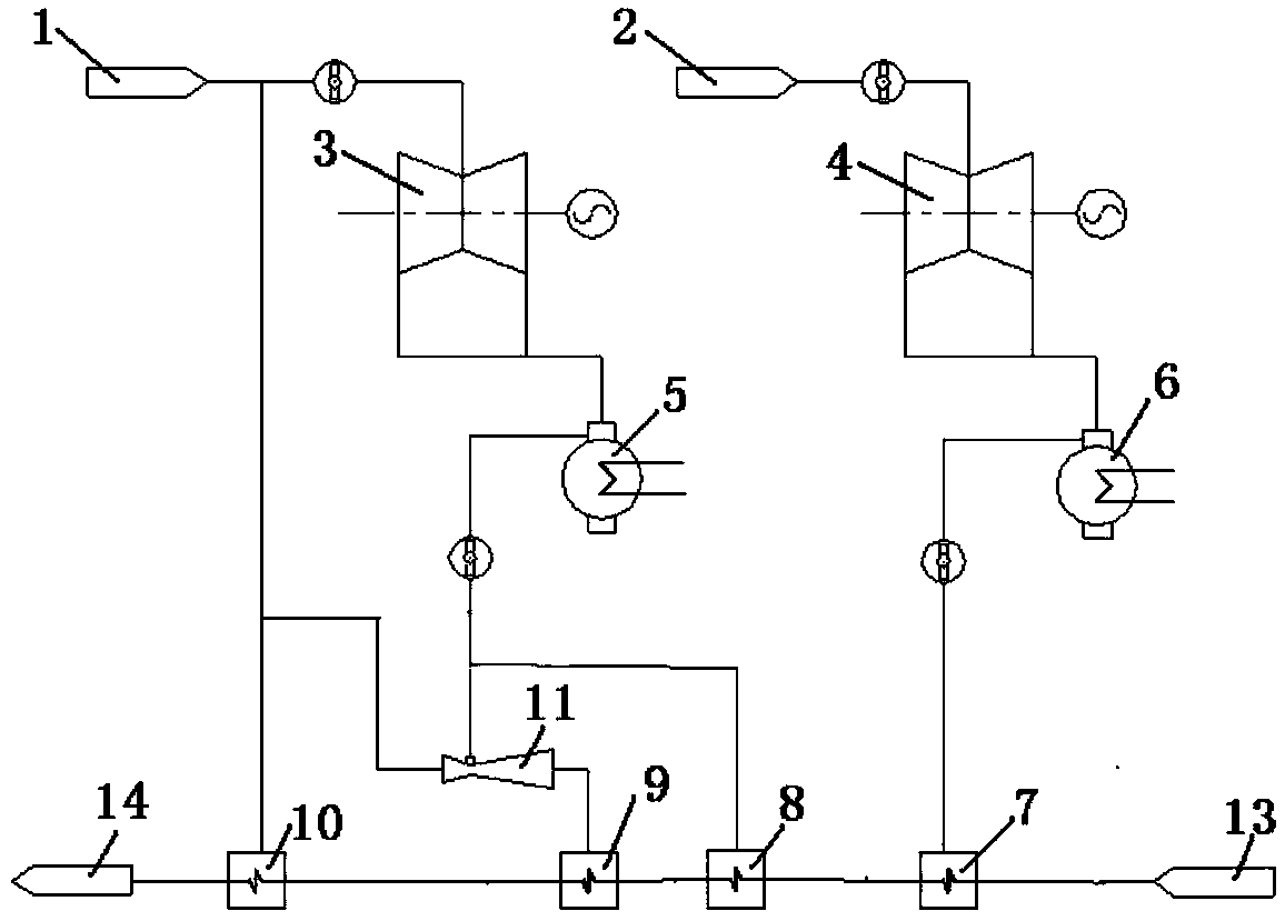
[0042] Embodiment two: if figure 2 As shown, the exhaust steam recovery and utilization heating system of steam booster type includes a first exhaust steam condenser 7, a second exhaust steam condenser 8, a steam booster 11, a steam booster condenser 9, and a heat network heater 10 , heating network water system, supporting piping system (including pipes, valves, pipe fittings, supports and hangers, expansion joints, etc.).

[0043] The exhaust steam outlet pipe of the low back pressure steam turbine is connected to the first exhaust steam condenser 7, and the exhaust steam outlet pipe of the high back pressure steam turbine is connected to the second exhaust steam condenser 8; The working (power) steam inlet; the high back pressure steam turbine exhaust steam outlet pipe is also connected to the suction steam port of the steam generator 11; the steam generator exhaust port is connected to the steam generator condenser 9; The heat network heater, the outlet water of the heat...

Embodiment 3

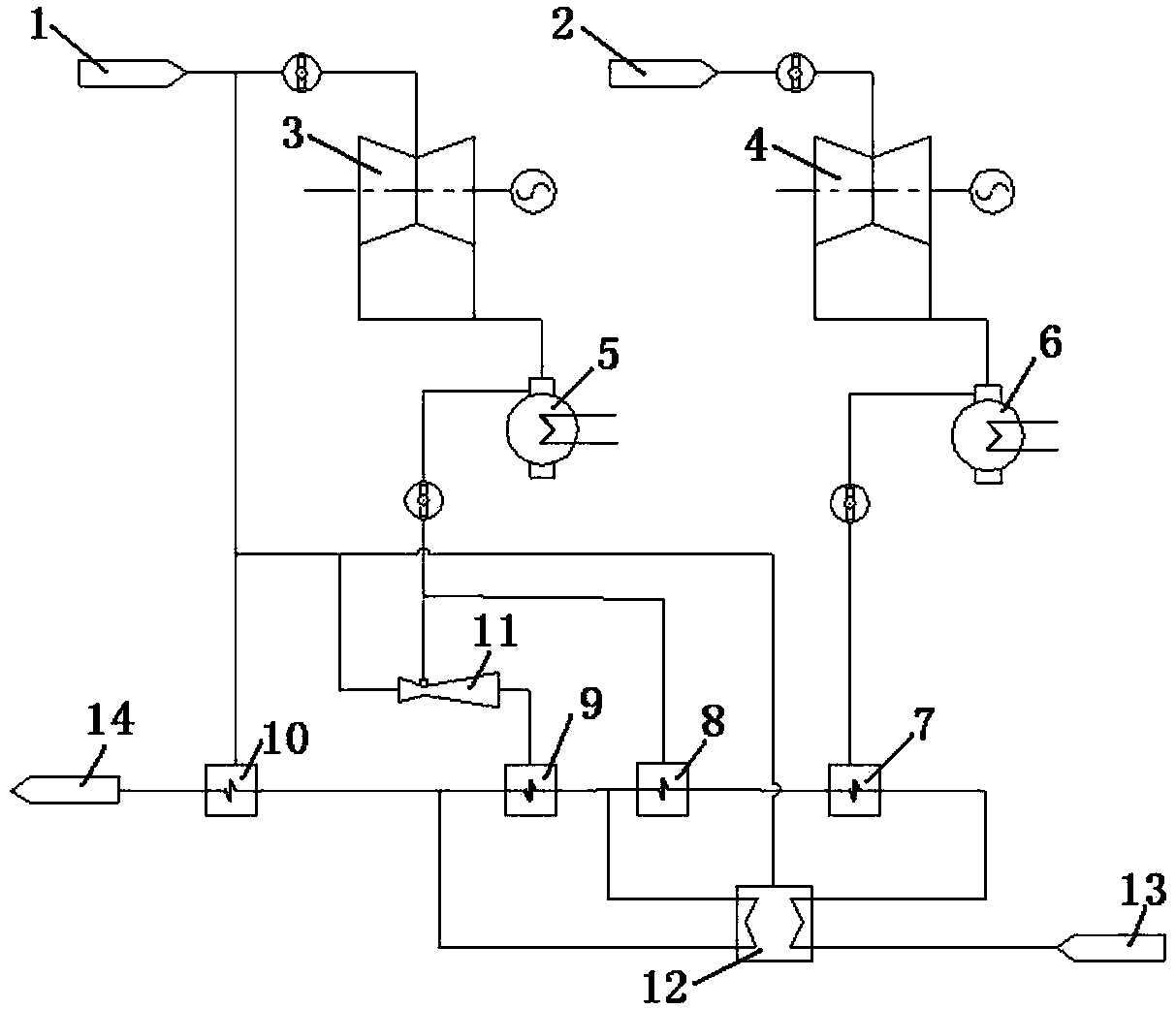
[0057] Such as image 3 , 4 As shown, on the basis of the second embodiment, the heat pump system can be further connected.

[0058] Its thermoelectric decoupling system for thermal power plants includes two steam turbines and corresponding two condensers or air-cooled islands, a exhaust steam extraction system, a steam generator type exhaust steam recovery and utilization heating system, and an absorption or compression heat pump heating system.

[0059] Steam generator type exhaust steam recovery and utilization heating system, including the first exhaust steam condenser 7, the second exhaust steam condenser 8, steam generator 11, steam generator condenser 9, heating network heater 10, heating network water System, supporting piping system (including pipes, valves, pipe fittings, supports and hangers, expansion joints, etc.).

[0060] Absorption or compression heat pump heating systems, including absorption or compression heat pump units; the heat release section of the he...


PUM


Abstract

A thermal power plant thermoelectric decoupling system comprises two steam turbines, two condensers or two air cooling islands corresponding to the two steam turbines, a dead steam extraction system and a dead steam recovery and heat supply system. Dead steam is extracted through the dead steam extraction system and conveyed to the dead steam recovery and heat supply system through a pipeline. Thedead steam recovery and heat supply system is connected with a heat supply pipe network and comprises a first dead steam condenser, a second dead steam condenser, a steam increase machine and a steamincrease machine condenser. Dead steam of the steam turbines is recovered for heat supply, the discharge steam amount during heat supply consumption is reduced, thus, main steam flow is reduced, thepower of a high-pressure cylinder and an intermediate-pressure cylinder is lowered, and large thermoelectric decoupling is achieved; cold end losses can be reduced, and energy conservation and emission reduction are achieved; the self-balancing function is achieved, the off-design condition performance is excellent, and the adaptability is high; the steam turbine loads are adjusted rapidly; and the complementarity with thermoelectric decoupling technologies of other types is good, and the combined operation effect is better.

Description

technical field [0001] The invention belongs to the field of thermal power plants, and in particular relates to a thermoelectric decoupling system of a thermal power plant. Background technique [0002] During the heating period in winter, urban central heating mainly relies on the combined heat and power units of thermal power plants, which not only supply heat but also generate electricity. The conventional heat supply mode of the thermal power plant, the heat supply heat mainly comes from the exhaust steam of the medium-pressure cylinder of the steam turbine, which is used to heat the circulating water of the heating network. The steam exhausted from the medium-pressure cylinder is the steam that has done work in the high-pressure cylinder and the medium-pressure cylinder of the steam turbine. If the mid-row steam is used for heating, this steam must do work in the high-pressure cylinder and the medium-pressure cylinder. That is, in order to realize and ensure heat supp...

Claims


Application Information

Patent Timeline
IPC IPC(8): F01K13/00F01K17/02F24D3/18
CPCF01K13/00F01K17/005F01K17/02F24D3/18
Inventor 曲恒
Owner UNI RISING BEIJING TECH CO LTD
Why Eureka
Try Eureka