
Synthetic fiber grating digital demodulation and regional temperature monitoring method and system

A fiber grating and area technology, which is applied in the field of the digital demodulation of the identical fiber grating and the area temperature monitoring method and the system thereof, can solve the problems such as the inability to effectively distinguish the wavelength and the temperature conversion of the variable, so as to avoid misjudgment of the reflection peak of the grating, and improve the The effect of efficiency

Active Publication Date: 2020-04-21
WUHAN WUTOS +1
View PDF4 Cites 0 Cited by
  • Summary
  • Abstract
  • Description
  • Claims
  • Application Information

AI Technical Summary

Problems solved by technology

[0004] The technical problem to be solved by the present invention is to provide a method that can effectively distinguish the wavelength variable and perform temperature conversion due to the overlap of center wavelengths in the prior art when using identical fiber gratings. Identical fiber grating digital demodulation and regional temperature monitoring method and system for temperature conversion

Method used


Image

  • Synthetic fiber grating digital demodulation and regional temperature monitoring method and system
  • Synthetic fiber grating digital demodulation and regional temperature monitoring method and system
  • Synthetic fiber grating digital demodulation and regional temperature monitoring method and system

Examples


Embodiment Construction

[0032] In order to make the object, technical solution and advantages of the present invention clearer, the present invention will be further described in detail below in conjunction with the accompanying drawings and embodiments. It should be understood that the specific embodiments described here are only used to explain the present invention, not to limit the present invention.

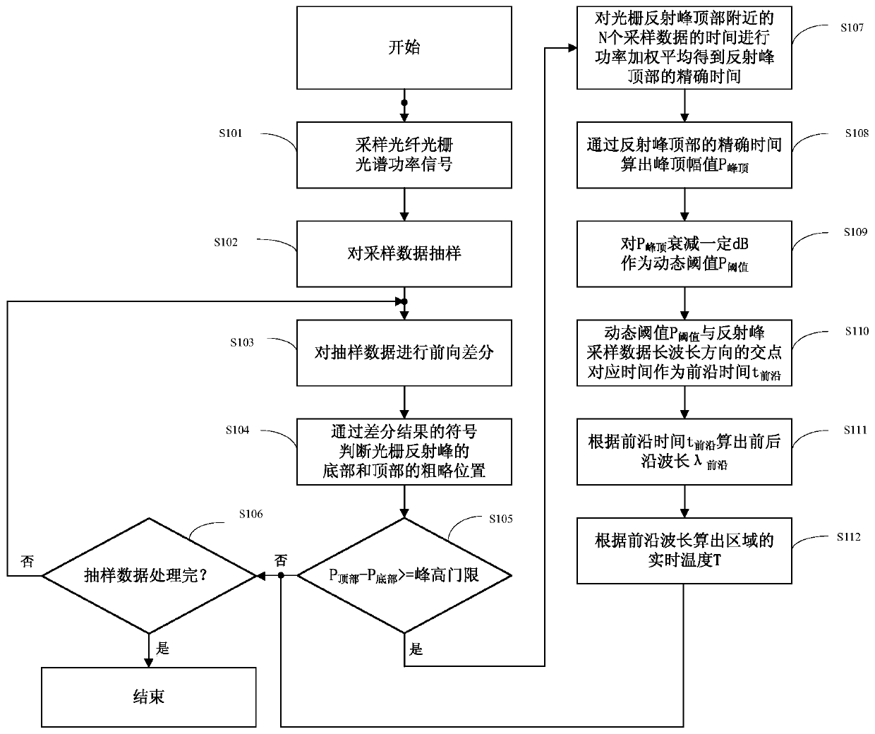
[0033] Such as figure 1 As shown, the embodiment of the present invention is identical to the fiber grating digital demodulation and regional temperature monitoring method including the following steps:

[0034] S101. Sampling the fiber grating reflection spectrum power signal to obtain sampling data at equal time intervals;

[0035] S102. Sampling the sampled data at equal intervals; the method of sampling the sampled data improves the efficiency of rough judgment of grating reflection peaks, avoids the problem of misjudgment of grating reflection peaks due to the jitter of dense sampling data an...


PUM


Abstract

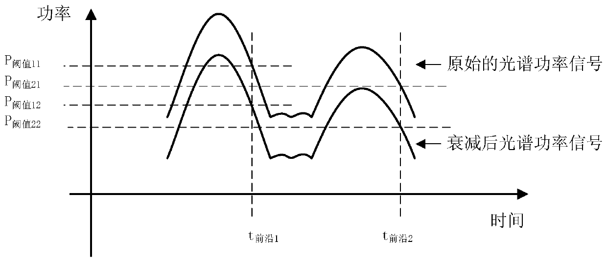
The invention discloses an identical optical fiber grating digital demodulation and regional temperature monitoring method and system thereof, wherein the method includes the following steps: sampling the optical fiber grating reflection spectrum power signal to obtain sampling data at equal time intervals; Sampling at equal intervals, and performing a forward difference on the sampled data, and judging the rough position of the bottom and top of the grating reflection peak through the sign change of the difference result; if the difference between the top power and the bottom power is greater than or equal to the preset peak height threshold, then the The peak is the reflection peak of the grating; the peak power of the reflection peak is calculated according to the sampling data near the top of the reflection peak of the grating; the dynamic threshold is obtained by attenuating the power of the peak top, and the time corresponding to the intersection point of the dynamic threshold and the sampling data of the reflection peak in the long wavelength direction As the front time, the front wavelength is calculated according to the front time; the real-time temperature of the area is calculated according to the front wavelength. The invention can effectively distinguish the variable of the wavelength and truly reflect the actual temperature change in the region.

Description

technical field [0001] The invention relates to digital demodulation of optical fiber gratings, in particular to an identical optical fiber grating digital demodulation and regional temperature monitoring method and system thereof. Background technique [0002] Fiber Bragg grating sensors are widely used in the field of temperature monitoring. At present, fiber gratings of different wavelengths are connected in series to form a sensing array, but this method is limited by the wavelength range of the demodulation instrument. For example, if the wavelength range of the demodulation instrument is 40nm, it can only carry up to 20 fiber grating sensors with different wavelengths. In practical applications, fire monitoring systems such as oil tanks and tunnels usually require temperature monitoring in a large area. The use of point-by-point fiber grating sensors faces the dual limitation of sensing range and sensor density. [0003] In order to solve the above problems, it is exp...

Claims


Application Information

Patent Timeline
Patent Type & Authority Patents(China)
IPC IPC(8): G01K11/32G01K11/3206
CPCG01K11/32
Inventor 钱磊董雷田卫东李凯
Owner WUHAN WUTOS
Learn More