Device and method for moving and rotating microsphere object

An object and spherical technology, applied in the field of devices for moving and rotating tiny spherical objects, can solve the problems of damage to tiny spherical objects, complexity of motion control, etc.

Active Publication Date: 2018-07-20
BEIJING INSTITUTE OF TECHNOLOGYGY
View PDF5 Cites 4 Cited by
  • Summary
  • Abstract
  • Description
  • Claims
  • Application Information

AI Technical Summary

Problems solved by technology

[0006] In order to solve the above problems, the present invention provides a device and method for moving and rotating tiny spherical objects. The vibration of the glass needle makes the water form a vortex, thereby dri

Method used


Image

  • Device and method for moving and rotating microsphere object
  • Device and method for moving and rotating microsphere object
  • Device and method for moving and rotating microsphere object

Examples


Embodiment 1

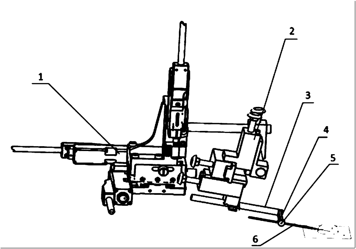
[0036] see figure 1 , which is a structural schematic diagram of a device for moving and rotating tiny spherical objects provided by the embodiment of the present application.

[0037] A device for moving and rotating tiny spherical objects, including a three-coordinate operating platform 1, a manual platform 2, a metal rod 3, a vibration mechanism 4, a metal connector 5, and a glass needle 6; the manual platform 2 is fixed on the three-coordinate On the operating platform 1, the three-coordinate operating platform 1 is used to adjust the position of the manual platform 2; one end of the metal rod 3 is fixed on the manual platform 2, and the other end is vertically connected with the vibration mechanism 4; the glass needle 6 is connected by a metal The part 5 is vertically connected with the end of the vibrating mechanism 4 away from the metal rod 3 , and the tip of the glass needle 6 is placed in the water drop 7 .

[0038] It should be noted that the three-coordinate operat...

Embodiment 2

[0050] Based on the above embodiments, the embodiment of the present application provides a method for moving and rotating a tiny spherical object. see Figure 4 , which is a flow chart of a method for moving and rotating a tiny spherical object provided by the embodiment of the present application.

[0051] A method for moving and rotating a tiny spherical object, applied to a device for moving and rotating a tiny spherical object, the device includes a three-coordinate operating platform 1, a manual platform 2, a metal rod 3, a vibration mechanism 4 and Glass needle 6, comprising the following steps:

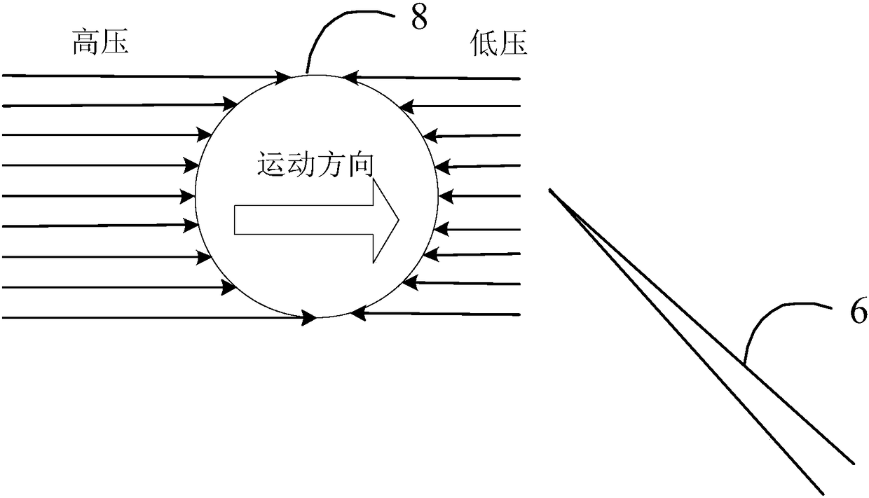
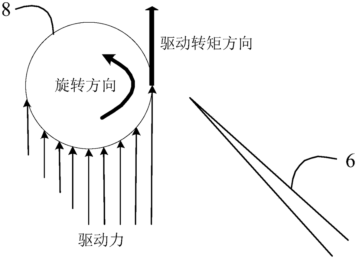
[0052] S401: Put the tiny spherical object 8 into the water drop 7, and place the water drop 7 containing the tiny spherical object 8 in the field of view of the microscope through the glass slide 9;

[0053] S402: Adjust the manual platform 2, put the tip of the glass needle 6 into the water drop 7, wherein the tip does not touch the tiny spherical object 8;

[0054] see ...


PUM


Abstract

The present invention provides a device and method for moving and rotating a microsphere object. A glass needle placed in water is driven by the vibration of a vibration mechanism to rotate at a highspeed to cause eddy current in the water, and finally the purpose of moving and rotating the microsphere object is achieved. Compared with an existing system which operates a microsphere object by a micromanipulator, the device has the advantages that the mechanical contact with the microsphere object is not needed, the direct or indirect damage to the microsphere object is avoided, an end of theglass needle can continuously rotate the microsphere object in an original place, the microsphere object is easily controlled within the field of view, and the observation is convenient. Compared withan existing system for operating a microsphere body in a micro-fluidic chip, the device has the advantages that the device is not limited by an operation task and the size of the microsphere object,and the operational flexibility is high.

Description

technical field [0001] The invention belongs to the technical field of micro-nano operation, and in particular relates to a device and method for moving and rotating micro-spherical objects. Background technique [0002] With the rapid development of micro-nano technology, micromanipulation technology plays an increasingly important role in the manufacture of complex mechanisms and single-cell manipulation. The rotation of tiny spherical objects is the most basic and important operation technique in micromanipulation. Both the microinjection of cells and the assembly of microstructures require multi-degree-of-freedom rotation and orientation of the target to adjust the posture to adapt to the corresponding operation. Therefore, it is very important to find a simple, efficient and continuous rotation method in the micro-scale range. [0003] The existing micro-manipulation technology for rotation is mainly the rotation operation of the micro-manipulator with multiple degrees...

Claims


Application Information

Patent Timeline
IPC IPC(8): G02B21/32
CPCG02B21/32
Inventor 刘晓明唐小庆李鹏云董胜男陈俊男黄强新井建生
Owner BEIJING INSTITUTE OF TECHNOLOGYGY
Why Eureka
Try Eureka