
Power balanced modulation method suitable for mixed cascaded H-bridge nine-level inverter

A technology of hybrid cascading and modulation method, which is applied in the direction of converting irreversible DC power input into AC power output, output power conversion device, AC power input into DC power output, etc., which can solve the problem of output power imbalance, system Increased maintenance costs, different battery life, etc., to achieve good output characteristics, improve DC voltage utilization, and improve practicability

Active Publication Date: 2018-07-20
NANJING UNIV OF AERONAUTICS & ASTRONAUTICS
View PDF5 Cites 4 Cited by
  • Summary
  • Abstract
  • Description
  • Claims
  • Application Information

AI Technical Summary

Problems solved by technology

The power distribution of the cascaded units is determined by the inherent characteristics of the modulation method. If the characteristics of the modulation method itself cause the output power of each cascaded unit to be unbalanced, it will cause the power supply to be unbalanced in charge and discharge, causing such as batteries, solar energy, etc. The voltage difference between the input power sources such as the battery increases, resulting in an increase in the harmonic content of the inverter output voltage, and at the same time causing the service life of each unit battery to be different, resulting in an increase in system maintenance costs
In addition, for a conversion system that uses a phase-shifting transformer and a diode uncontrolled rectifier bridge to provide a DC source on the DC side, when the output power of the cascaded units is unbalanced, it becomes difficult to remove the input-side harmonic current by designing a phase-shifting transformer. difficulty

Method used


Image

  • Power balanced modulation method suitable for mixed cascaded H-bridge nine-level inverter
  • Power balanced modulation method suitable for mixed cascaded H-bridge nine-level inverter
  • Power balanced modulation method suitable for mixed cascaded H-bridge nine-level inverter

Examples


Embodiment Construction

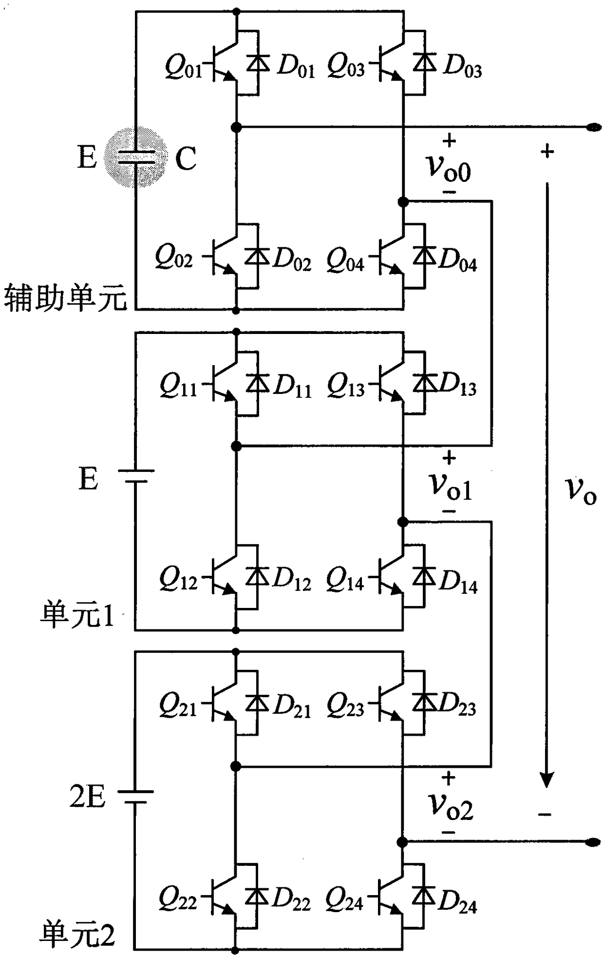
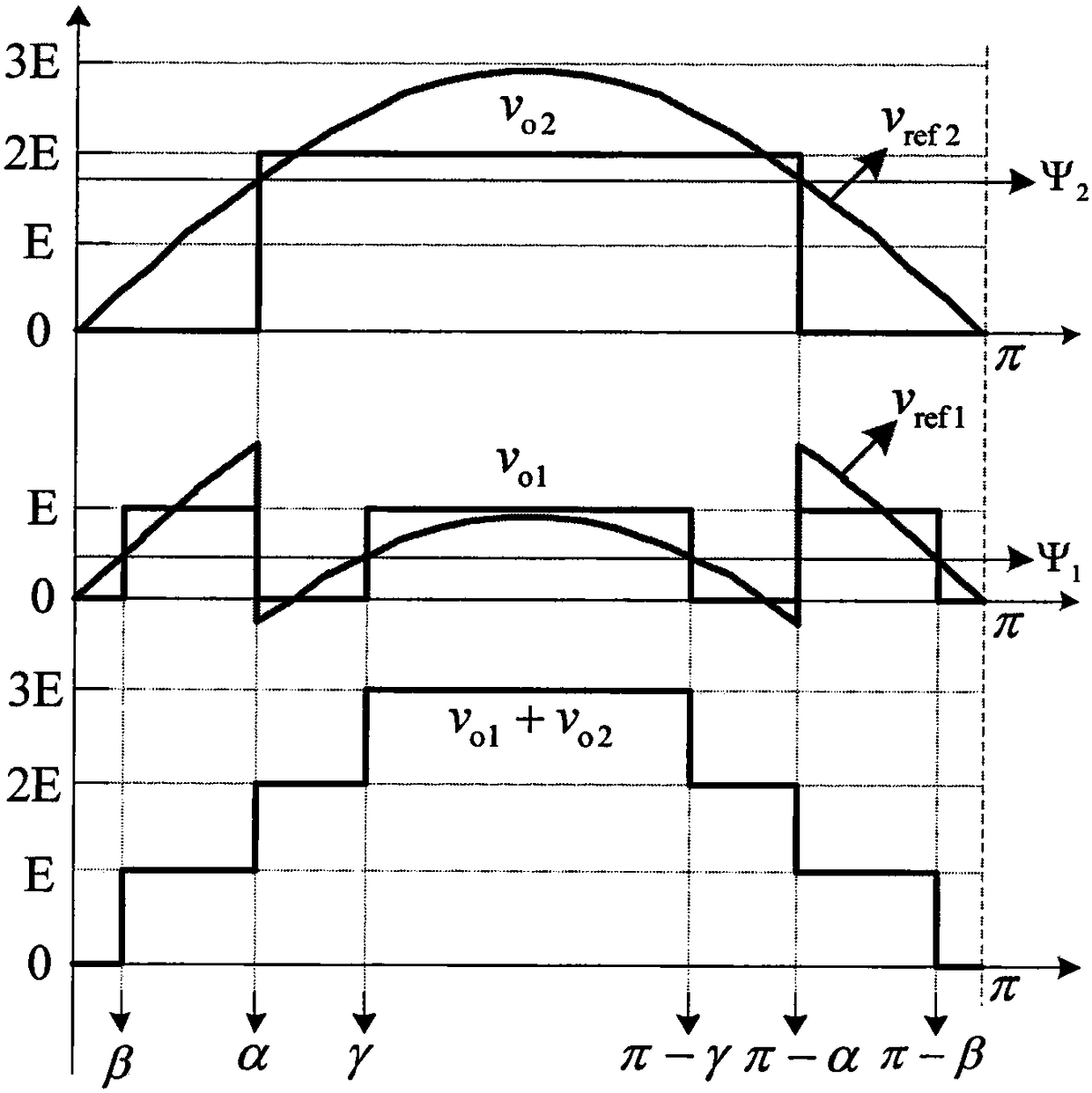
[0022] The output level synthesis principle of the main power unit of the power balance modulation method suitable for the hybrid cascaded H-bridge nine-level inverter proposed by the present invention is as follows: figure 2 shown.

[0023] Taking the positive half cycle as an example, the output voltage of unit 2 is determined by the switch angle α, which outputs level 2E in the interval [α, π-α], and outputs 0 level in the rest of the interval; the output voltage of unit 1 is determined by the switch The angles α, β and γ are jointly determined, and it outputs level E in the intervals [β, α], [γ, π-γ] and [π-α, π-β], and outputs 0 level in the remaining intervals. Here, the switching angle α is determined by the modulation wave v of unit 2 ref2 Comparison level Ψ with unit 2 2 The intersection point is determined; the switching angles β and γ are determined by the modulating wave v of unit 1 ref1 Comparison level Ψ with unit 1 1 The intersection point is determined.

...


PUM


Abstract

The invention discloses a power balanced modulation method suitable for a mixed cascaded H-bridge nine-level inverter. The method comprises that an absolute value is taken from a sinusoidal modulatedwave vref to obtain a modulated wave vref2 of a unit 2, and a modulated wave vref1 of a unit 1 and a modulated wave vref0 of an auxiliary unit are obtained via comparison and operation. The modulatedwave vref2 intersects with a comparison level psi2 to obtain a logic pulse signal C, the modulated wave vref1 intersects with the comparison level psi1 to obtain a logic pulse signal B, the modulatedwave vref0 is compared with triangular carrier waves vtra1 and vtra2 to obtain logic pulse signals A1 and A2, and the sinusoidal modulated wave vref is compared with a zero voltage to obtain a polar pulse signal D. A driving logical distribution unit generates an optimized PWM driving signal according to the logic pulse signals and the polar pulse signal. Via the method, it is ensured that the mixed cascaded H-bridge nine-level inverter has a good output characteristic within a full modulation ratio range, power of the two main power units is controlled in a balanced way, and the multi-level inverter is more practical.

Description

technical field [0001] The invention belongs to the technical field of multi-level converter PWM, in particular to a power balance modulation method suitable for a hybrid cascaded H-bridge nine-level inverter with a voltage ratio of 1:1:2. Background technique [0002] In recent years, multilevel inverters have become a research hotspot in power conversion in medium and high voltage applications due to their advantages such as low voltage stress of switching devices, low harmonic content of output voltage, and low electromagnetic interference. However, as the number of inverter output levels increases, traditional multilevel inverters require more power devices and complex structures, resulting in problems such as large size, low efficiency, and high cost, which greatly limit its practical application. scope. The hybrid cascaded multilevel inverter is a new type of multilevel inverter proposed to solve these shortcomings of the traditional multilevel inverter. It can output...

Claims


Application Information

Patent Timeline
Patent Type & Authority Applications(China)
IPC IPC(8): H02M7/49
CPCH02M7/49H02M7/4835
Inventor 陈仲许亚明刘亚云那显龙
Owner NANJING UNIV OF AERONAUTICS & ASTRONAUTICS
Learn More