Driving structure of travelling wave micro motor

A driving structure and micro-motor technology, applied in the direction of piezoelectric effect/electrostrictive or magnetostrictive motors, generators/motors, electrical components, etc., can solve the problem of fewer connections between the driving structure and the substrate and increasing the driving structure The difficulty of preparation and the difficulty of making the device size small, etc., to achieve the effect of guaranteed performance, small thickness, and reduced stiffness

Active Publication Date: 2018-07-20
INST OF ELECTRONICS ENG CHINA ACAD OF ENG PHYSICS
View PDF11 Cites 7 Cited by
  • Summary
  • Abstract
  • Description
  • Claims
  • Application Information

AI Technical Summary

Problems solved by technology

[0003] However, the device performance of existing traveling-wave micromotors cannot meet people's expectations. The main reasons are as follows: First, in order to improve the output of traveling-wave micromotors, it is necessary to make them have smaller stiffness and larger elastic modulus, which requires fewer and thinner joints between the driving structure and the substrate, which undoubtedly increases the difficulty of preparing the driving structure and makes the driving structure easy to break; secondly, the properties of piezoelectric materials have always restricted the An important factor in the development of micro-motors is limited by the performance of piezoelectric films. Piezoelectric ceramics are often used as functional materials in piezoelectric traveling-wave micro-motors, which makes it difficult to reduce the size of the device and seriously affects the integration of micro-motors; During the working process of the micromotor, it is necessary to excite continuous traveling waves on the surface of the driving structure. The transmission of traveling waves means the transmission of energy. However, limited by the structure and working mode of the traveling wave micromotor, the vibration generated by the driving structure part It is easy to spread around in the form of waves, and finally dissipate through the substrate, which makes the power consumption of traveling wave micromotors generally large, and the quality factor-Q value is low

Method used


Image

  • Driving structure of travelling wave micro motor
  • Driving structure of travelling wave micro motor
  • Driving structure of travelling wave micro motor

Examples


Embodiment Construction

[0022] The following will clearly and completely describe the technical solutions in the embodiments of the present invention with reference to the accompanying drawings in the embodiments of the present invention. Obviously, the described embodiments are only some, not all, embodiments of the present invention. Based on the embodiments of the present invention, all other embodiments obtained by persons of ordinary skill in the art without making creative efforts belong to the protection scope of the present invention.

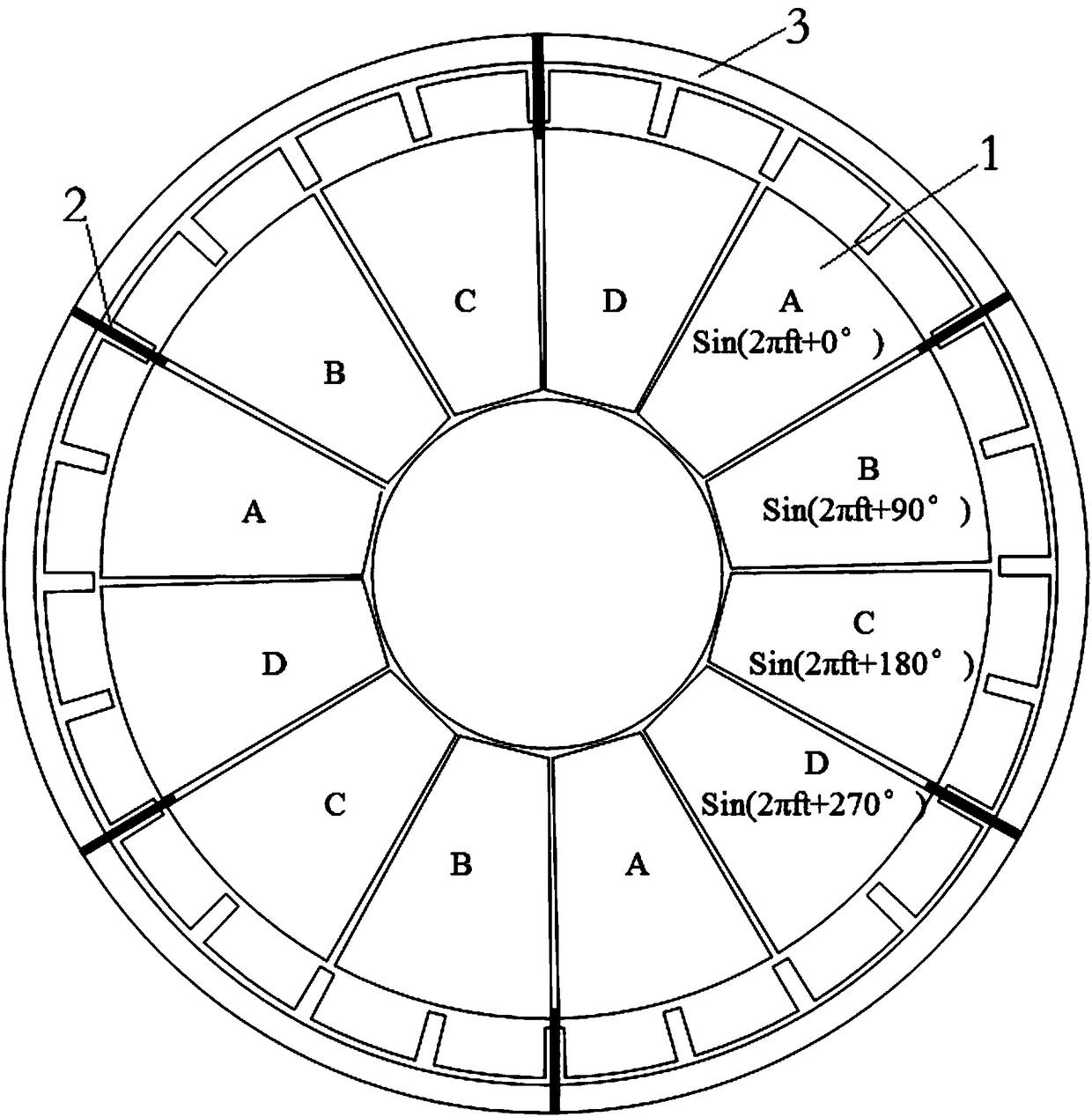
[0023] The purpose of the present invention is to provide a driving structure of the traveling wave micromotor to solve the problems existing in the prior art, reduce the power consumption of the traveling wave micromotor and increase the output of the traveling wave micromotor.

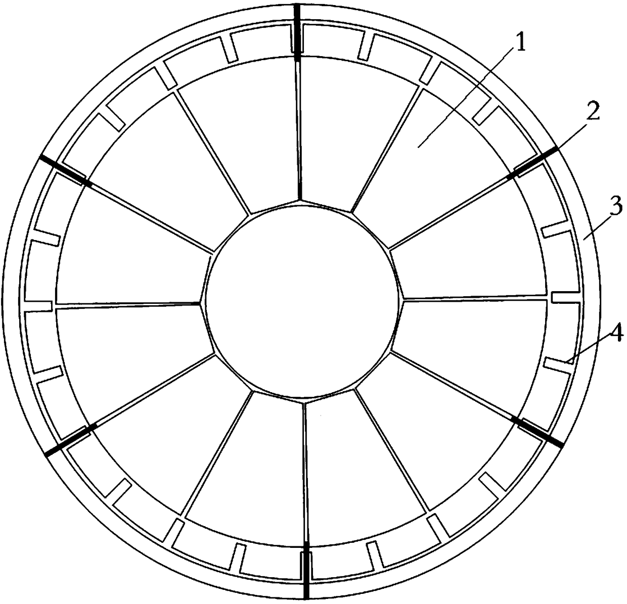
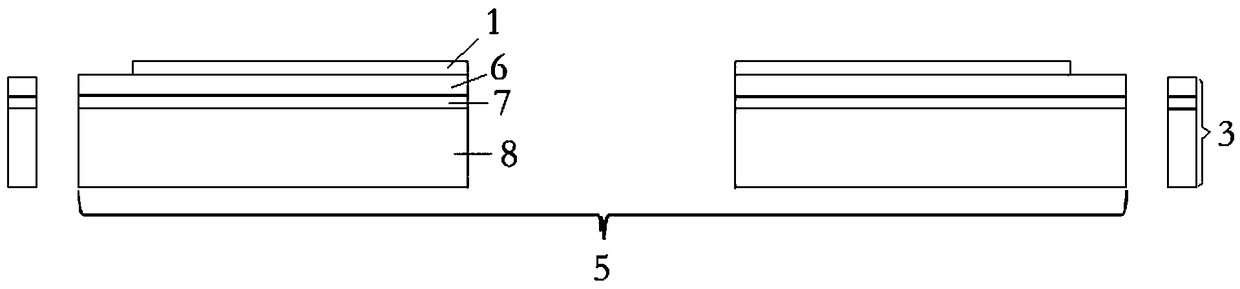
[0024] The present invention provides a driving structure of a traveling wave micro-motor, which includes an annular support frame and an annular body placed in the annular support fr...


PUM


Abstract

The invention discloses a driving structure of a travelling wave micro motor. The driving structure comprises an annular support frame and a circular annular body, wherein the circular annular body isarranged in the annular support frame, the annular support frame and the circular annular body are connected by a plurality of support beams, a first electrode layer and a matrix are arranged on thecircular annular body from top to bottom, the first electrode layer comprises a plurality of fan-shaped electrodes which are arranged in annular way, an interval is reserved between two adjacent fan-shaped electrodes, the external diameter of each fan-shaped electrode is smaller than the external diameter of the matrix, a plurality of grooves are formed in a side wall of the matrix, openings of the grooves are arranged in central lines of the fan-shaped electrodes and an interface line of two adjacent fan-shaped electrodes, and the support beams are uniformly distributed in the grooves. In thedriving structure of the travelling wave micro motor, the vibration energy of the driving structure is limited in frame energy by the support beams and the annular support frame, the support beams are fixed at a node of the travelling wave micro motor, the vibration energy is further prevented from diffusing outwards, the energy loss is substantially reduced, and the Q value of the driving structure is increased.

Description

technical field [0001] The invention relates to the technical field of piezoelectric micromotors, in particular to a driving structure of a traveling wave micromotor. Background technique [0002] Traveling-wave micromotor is a new type of micro-actuator element, which has great application potential in the field of MEMS. Currently commonly used traveling wave micromotors can be divided into electrostatic micromotors, electromagnetic micromotors, and piezoelectric micromotors according to the type of driving material. Among them, the piezoelectric micromotor has the most application prospect. Thanks to the inverse piezoelectric property of the piezoelectric material, the piezoelectric micromotor can achieve a large driving capacity under the working voltage of 10V. At present, the common piezoelectric micromotor adopts the disc structure, and the standing waves of the same frequency are generated by time-sharing on different annular sectors of the disc, so as to excite the ...

Claims


Application Information

Patent Timeline
Patent Type & Authority Applications(China)
IPC IPC(8): H02N2/16H02N2/12
CPCH02N2/12H02N2/163
Inventor 孙翔宇杜亦佳代刚陈余弓冬冬
Owner INST OF ELECTRONICS ENG CHINA ACAD OF ENG PHYSICS
Why Eureka
Try Eureka