Difference-frequency electric stimulation device, system and method

A technology of electrical stimulation and equipment, applied in the field of medical devices, can solve problems such as poor applicability, complications, cerebral hemorrhage and infection

Inactive Publication Date: 2018-07-24
北京大智商医疗器械有限公司
View PDF5 Cites 5 Cited by
  • Summary
  • Abstract
  • Description
  • Claims
  • Application Information

AI Technical Summary

Problems solved by technology

However, the operation of implanting electrodes has risks such as cerebral hemorrhage and infection, and it is very likely to

Method used


Image

  • Difference-frequency electric stimulation device, system and method
  • Difference-frequency electric stimulation device, system and method
  • Difference-frequency electric stimulation device, system and method

Examples


Embodiment 1

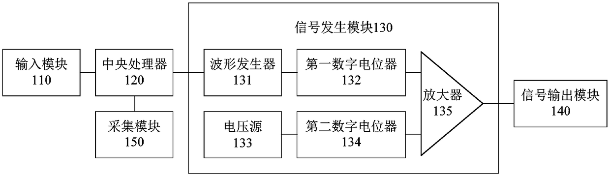
[0035] figure 1 A circuit connection schematic diagram of a difference-frequency electrical stimulation device provided by an embodiment of the present invention, as shown in figure 1 As shown, the beat frequency electrical stimulation device includes an input module 110 , a central processing unit 120 , a signal generating module 130 and a signal output module 140 connected in sequence. The signal output module 140 includes a plurality of output interfaces, and each output interface is connected to a pair of electrodes; at least two pairs of electrodes are arranged on the stimulated part of the object to be stimulated. The stimulated object can be human or animal, such as mouse, rabbit, sheep, dog, etc. The difference-frequency electrical stimulation device performs weak electrical stimulation on specific areas of the brain (stimulated parts) through at least two pairs of electrodes. The international 10% system electrode placement method determines the location of the stim...

Embodiment 2

[0077] Figure 7 A structural schematic diagram of a difference-frequency electrical stimulation system provided for an embodiment of the present invention, as shown in Figure 7 As shown, the differential frequency electrical stimulation system includes the differential frequency electrical stimulation device 71 as in the first embodiment above, and also includes a host computer 72 ; the host computer 72 is communicatively connected with the differential frequency electrical stimulation device 71 .

[0078] Specifically, the upper computer 72 and the differential frequency electrical stimulation device 71 can be connected through a wireless communication module, or through a serial port, which is not limited here. The difference frequency electrical stimulation device 71 can also be called a lower computer. Display items can be set on the host computer 72, such as electrode selection, electric field display, and the like. Before stimulation, the host computer 72 detects the...

Embodiment 3

[0100] This embodiment also provides a difference frequency electrical stimulation method, which is applied to the upper computer 72 of the difference frequency electrical stimulation system in the second embodiment above. Figure 9 A schematic flow chart of a difference-frequency electrical stimulation method provided by an embodiment of the present invention, such as Figure 9 As shown, the method includes the following steps:

[0101] Step S901, acquiring the stimulation parameters sent by the differential frequency electrical stimulation device, and determining the electrode combination corresponding to the stimulation parameters.

[0102] Step S902, acquiring the resistance of the stimulated object sent by the differential frequency electrical stimulation device, and judging whether the above-mentioned electrode combination is connected according to the resistance of the stimulated object.

[0103] Specifically, it is judged whether the resistance of the stimulated objec...


PUM

PropertyMeasurementUnit
The inside diameter ofaaaaaaaaaa
Diameteraaaaaaaaaa
Diameteraaaaaaaaaa

Abstract

The invention provides a difference-frequency electric stimulation device, system and method. The device comprises an input module, a central processor, a signal generation module and a signal outputmodule connected sequentially; the signal output module comprises multiple output interfaces, and each output interface is connected with one pair of electrodes; and at least two pairs of electrodes are arranged in a stimulated position of a stimulated object. Via the two or more pairs of electrodes, the electric stimulation device transmits two or more currents of different frequencies to the stimulated object, a low-frequency modulated pulse current (namely a difference frequency signal) is generated in a crossed area of the currents, and the low-frequency modulated current has an adjustmenteffect for brain cells. The low-frequency modulated current can stimulate the deep of the brain without influence on superficial neuron cells, and thus, the defect that the low-frequency current cannot reach deep in the brain is overcome, the risk of operation is reduced via an non-intrusion feature, the safety is high, a user is more willing to accept the device, and the applicability is high.

Description

technical field [0001] The invention relates to the technical field of medical devices, in particular to a difference-frequency electrical stimulation device, system and method. Background technique [0002] Due to the fast pace of modern life and high work pressure, many people are troubled by some brain diseases. In addition, the elderly are facing the problem of gradual decline in cognitive function. Therefore, people hope to improve the treatment of some brain diseases through some feasible technologies. cognitive ability, improve their brain function. [0003] At present, electrical stimulation of the brain is usually performed to treat brain diseases and improve brain function. Because brain cells with low-pass characteristics can only respond to currents with a low frequency (frequency range: about 1-200Hz), and low-frequency currents cannot directly penetrate into the brain tissue without affecting other brain regions, traditional deep brain stimulation (DBS) , dee...

Claims


Application Information

Patent Timeline
IPC IPC(8): A61N1/36
CPCA61N1/36014
Inventor 闫天翼陈端端沈亚奇李章平吴景龙
Owner 北京大智商医疗器械有限公司
Why Eureka
Try Eureka