Propellant self-driven device of MEMS electrospray thruster

A propellant and thruster technology, which is applied in the field of propellant drive devices, can solve problems such as limited thrust accuracy and supply accuracy, and achieve the effects of reducing processing difficulty, improving flow accuracy, and realizing modular design

Inactive Publication Date: 2018-07-24
BEIJING INST OF CONTROL ENG
View PDF4 Cites 7 Cited by
  • Summary
  • Abstract
  • Description
  • Claims
  • Application Information

AI Technical Summary

Problems solved by technology

[0005] The technical problem solved by the present invention is: to overcome the deficiencies of the prior art, and to propose a MEMS electrospray thruster propellant drive device, which solves the problem that the original electrosp...

Method used


Image

  • Propellant self-driven device of MEMS electrospray thruster
  • Propellant self-driven device of MEMS electrospray thruster
  • Propellant self-driven device of MEMS electrospray thruster

Examples


Embodiment Construction

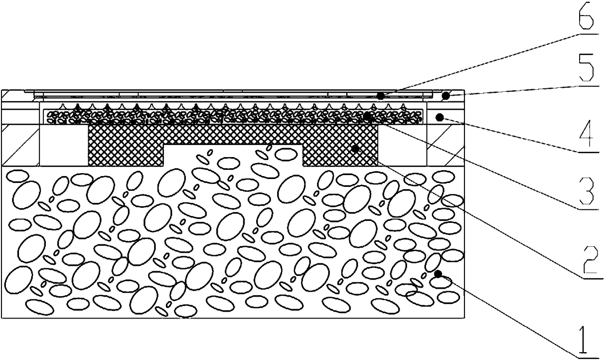
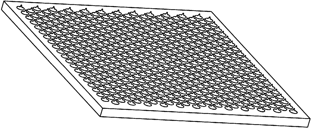
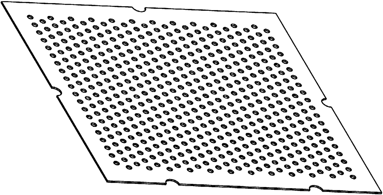
[0024] Aiming at the space propulsion requirements of micro-nano satellites, the present invention proposes a MEMS electrospray thruster propellant self-driving device, such as figure 1 As shown, it includes: a tank 1 , a connection device 2 , a porous emitter 3 , an insulating alignment frame 4 , a silicon mounting frame 5 , and an extraction electrode 6 . The hollow part inside the storage tank 1 stores the propellant liquid, and the insulating alignment frame 4 is installed on the upper part of the storage tank 1; the extraction electrode 6 is installed on the insulating alignment frame 4 through the installation silicon frame 5 installed on the edge of the extraction electrode 6; the porous emitter 3. The connection device 2 is installed between the extraction pole 6 and the storage tank 1 , and the porous emitter 3 is connected to the upper part of the storage tank 1 through the connection device 2 .

[0025] The storage tank 1 has a cubic structure and is made of a porou...


PUM

PropertyMeasurementUnit
Apertureaaaaaaaaaa
Apertureaaaaaaaaaa

Abstract

A propellant self-driven device of an MEMS electrospray thruster comprises a storage box (1), a connecting device (2), a porous emitter electrode (3), an insulating alignment frame (4), a mounting silicon frame (5) and an extraction electrode (6), wherein propellant liquid is stored in the hollow part inside the storage box (1); the insulating alignment frame (4) is mounted at the upper part of the storage box (1); the extraction electrode (6) is mounted on the insulating alignment frame (4) through the mounting silicon frame (5) mounted at the edge of the extraction electrode (6); the porousemitter electrode (3) and the connecting device (2) are mounted between the extraction electrode (6) and the storage box (1); the porous emitter electrode (3) is connected to the upper part of the storage box (1) through the connecting device (2); and there is a potential difference between the porous emitter electrode (3) and the extraction electrode (6). The propellant self-driven device of theMEMS electrospray thruster solves the problem that an original electrospray propulsion system needs to be equipped with special propellant supply management devices such as a micro pump and a micro valve, and that the thrust precision is largely limited by the propellant supply precision of the micro valve and other mechanisms.

Description

technical field [0001] The invention relates to the technical field of liquid propulsion, in particular to a propellant driving device. Background technique [0002] Micro-nano satellites are an important direction for the development of satellites in the future. Micro-nano satellites have the advantages of low cost, short development cycle, strong expansion capability, flexible launch methods, etc., and are small in size and flexible in action; Or fly in formation to perform more complex space missions. This year, it has attracted the attention of various space powers, and the number of launches has increased year by year. [0003] However, with the increase in the complexity of micro-nano-satellite missions and the increase in the design life in orbit, corresponding propulsion modules will be required to complete their attitude control and orbit-keeping tasks; on the other hand, as the number of micro-nano-satellites increases, the Space resources will become tight, and ...

Claims


Application Information

Patent Timeline
IPC IPC(8): B64G1/40F03H99/00
CPCB64G1/401F03H99/00
Inventor 耿金越龙军刘旭辉沈岩
Owner BEIJING INST OF CONTROL ENG
Why Eureka
Try Eureka