Fast combination locking-type scaffold system
A scaffolding and combination lock technology, applied in the connection of scaffolding, housing structure support, housing structure support and other directions, can solve the problems of frame shaking, limited overlap height, collapse, etc., and achieve the effect of convenient assembly and high safety.
- Summary
- Abstract
- Description
- Claims
- Application Information
AI Technical Summary
Problems solved by technology
Method used
Image
Examples
Embodiment 1
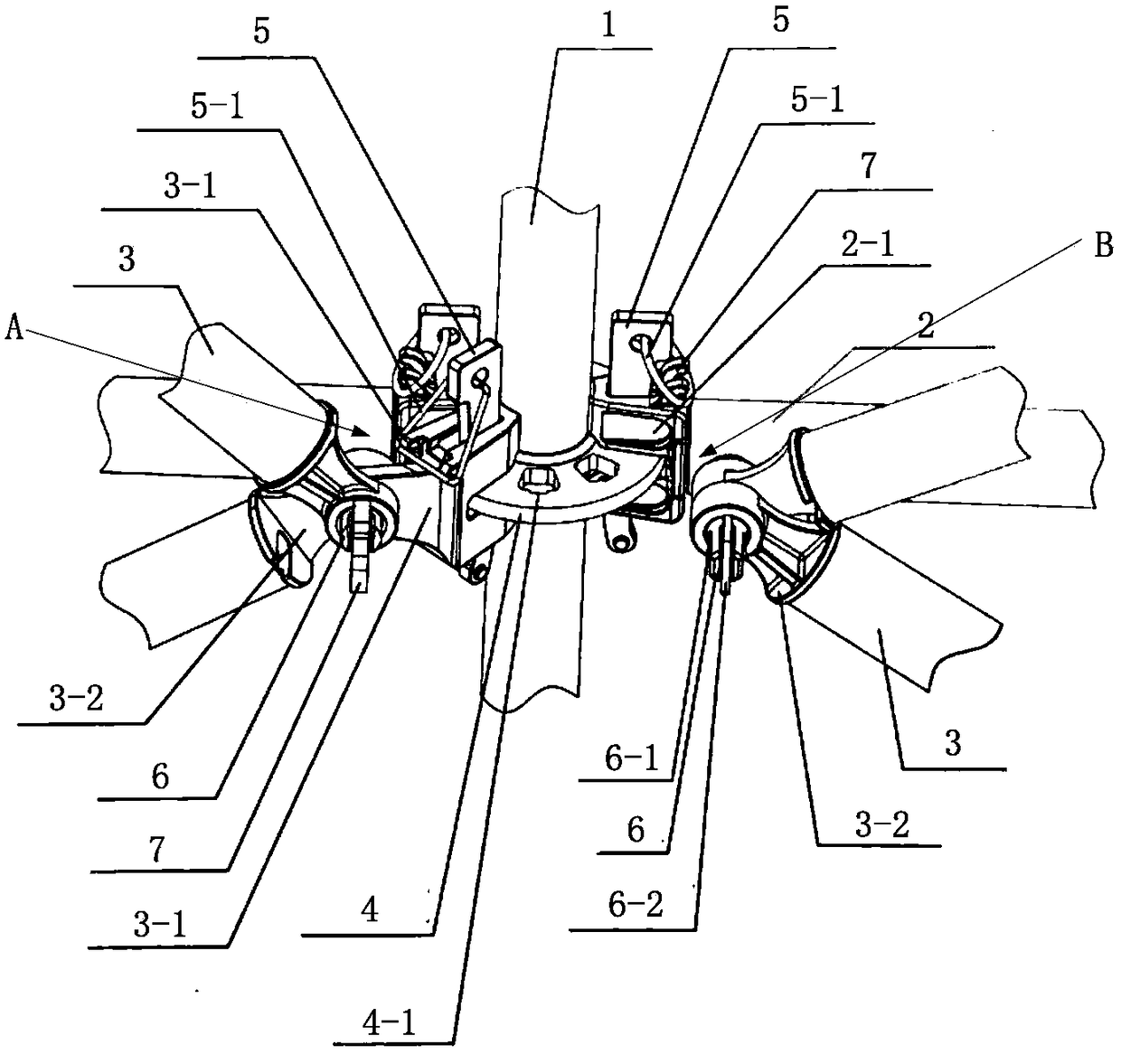
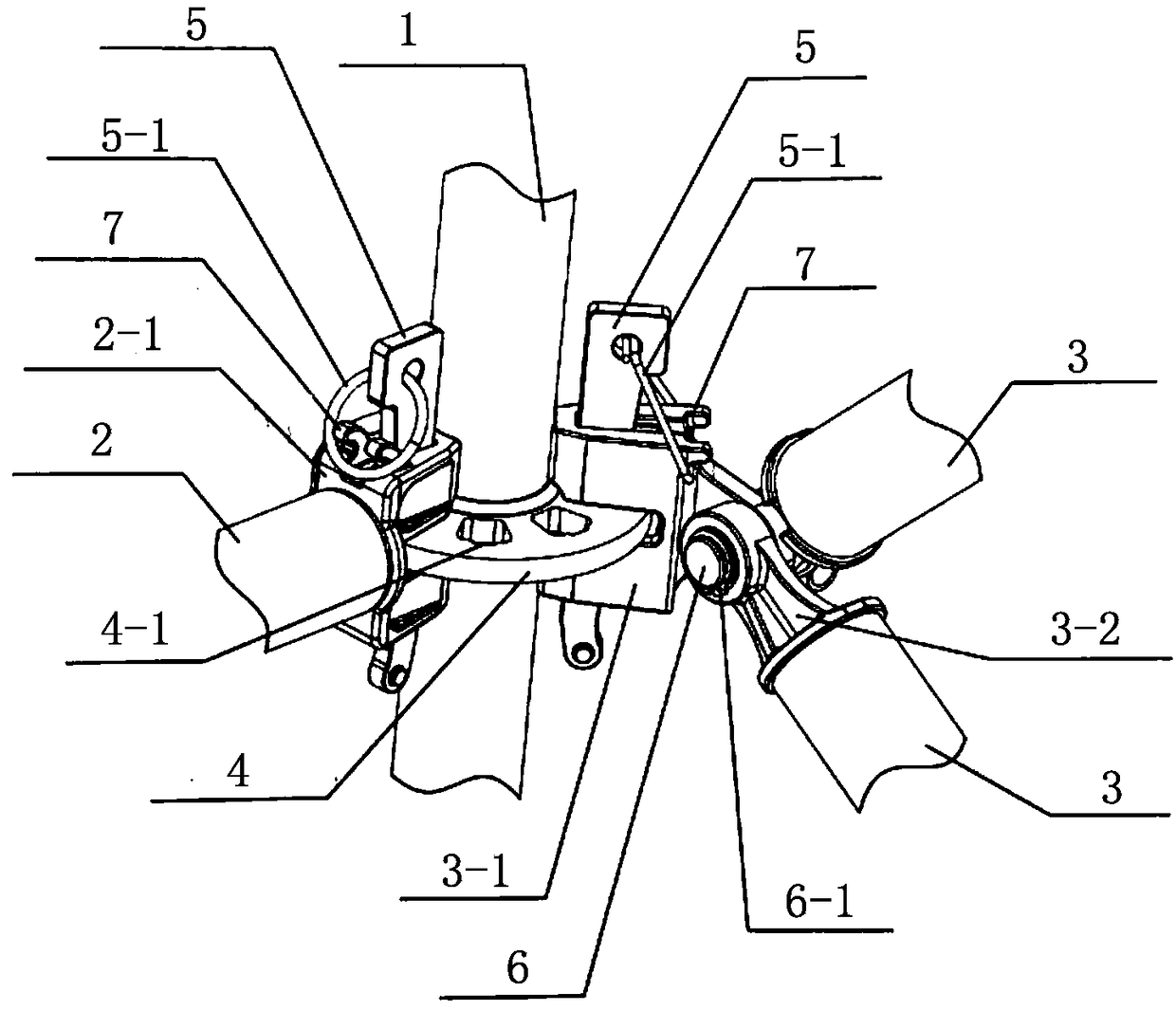
[0044] Embodiment 1: The oblique rod 3 is connected to the vertical rod 1 through the cooperation of the oblique lock head 3-1,
[0045] The front end of the oblique lock head 3-1 is open and engaged with the connection plate 4 of the vertical rod 1, and the rear end is provided with a connecting platform with a conjoined lock pin 6; the front end of the oblique rod 3 is fixedly connected with the oblique rod joint 3 with a sleeve -2; the casing of the oblique rod joint 3-2 is inserted into the conjoined lock pin 6 and then locked with the limiter 6-2 to realize the connection between the oblique rod 3 and the vertical rod 1; in a preferred solution, the oblique rod Joint 3-2 is provided with several bushings, refer to Figure 4 , the oblique rod 3 can be connected with the lock pin 6 through the bushing at different positions, so as to realize the adaptive selection of the connection position between the oblique rod 3 and the horizontal rod 2 or the vertical rod 1, and can co...
Embodiment 2
[0046] Embodiment 2: The inclined bar 3 is directly connected with the vertical bar 1 / horizontal bar 2 through the lock pin 6,
[0047] The locking pin 6 is fixed on the vertical rod 1 / horizontal rod 2, and is convenient to be inserted into the casing of the diagonal rod joint 3-2, so as to realize the connection between the diagonal rod 3 and the vertical rod 1 / horizontal rod 2.
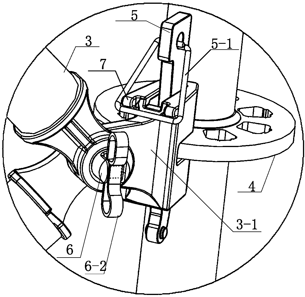
[0048] The front end of the locking pin 6 is provided with a "U"-shaped opening, and a pin shaft 6-1 perpendicular to the opening direction is arranged in the "U"-shaped opening, and a stopper 6-2 is installed on the pin shaft 6-1. The limiter 6-2 is a spring stopper, a latch or a locking piece;
Embodiment 3
[0050] Such as Figure 6 , Figure 7 As shown, the limiting member 6-2 is a locking plate, and the locking plate is provided with an annular space and inserted into the pin shaft 6-1 to realize rotation and up and down movement, so as to ensure that it is in the same axial direction as the locking pin 6, that is, in order The 3-2 sleeve of the inclined rod joint can be inserted in the vertical position, and the 3-2 sleeve of the inclined rod joint can be prevented from falling off when standing;
PUM
 Abstract
Description
Claims
Application Information
 - R&D
- Intellectual Property
- Life Sciences
- Materials
- Tech Scout
- Unparalleled Data Quality
- Higher Quality Content
- 60% Fewer Hallucinations
Browse by: Latest US Patents, China's latest patents, Technical Efficacy Thesaurus, Application Domain, Technology Topic, Popular Technical Reports.
© 2025 PatSnap. All rights reserved.Legal|Privacy policy|Modern Slavery Act Transparency Statement|Sitemap|About US| Contact US: help@patsnap.com


