

Heat conduction interface material and preparation method thereof
An interface material and heat-conducting layer technology, which is used in heat exchange materials, flat products, chemical instruments and methods, etc., can solve the problem of not completely wrapping the heat-conducting channel of the glass fiber reinforced layer, affecting the combination of the heat-conducting sheet and the glass-fiber reinforced layer, and the thermal conductivity. The coefficient is only 0.3W, etc., to achieve the effect of portability, small equipment space, and minimization of volume
- Summary
- Abstract
- Description
- Claims
- Application Information
AI Technical Summary
Problems solved by technology
Method used
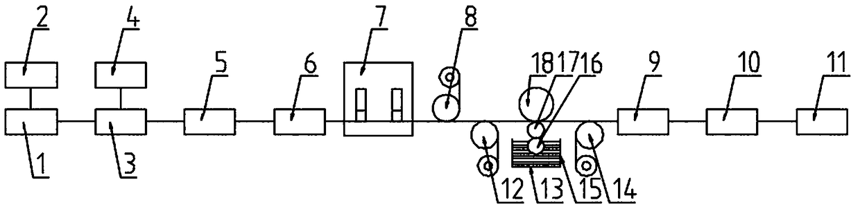
Image

Examples
Embodiment 1
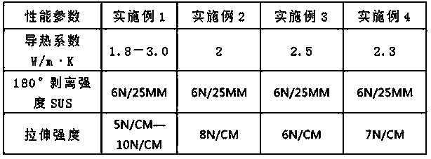
[0038] This embodiment provides a method for preparing a thermal interface material, including the following steps:
[0039] (1) Distributed vacuuming
[0040] Add liquid silica gel, coupling agent, heat-conducting powder, flame retardant, inhibitor and platinum catalyst to the dispersing equipment to disperse and vacuumize to obtain a heat-conducting mixture after dispersing evenly. Among them, the mass parts of each component are: 15-30 parts of liquid silica gel, 0.3-0.6 parts of coupling agent, 20-60 parts of 45-micron particle size thermal conductive powder, 40-80 parts of 15-micron particle size thermal conductive powder, 5 50-100 parts of thermal conductive powder with micron particle size, 15-25 parts of flame retardant, 0.04-0.06 parts of inhibitor, 0.08-1.1 parts of platinum catalyst; the thermal conductive powder is alumina, and the flame retardant is aluminum hydroxide.
[0041] In this step, in order to disperse all the raw materials better and faster, the disper...
Embodiment 2
[0065] This embodiment provides a method for preparing a thermal interface material, including the following steps:
[0066] (1) Distributed vacuuming
[0067] Add liquid silica gel, coupling agent, heat-conducting powder, flame retardant, inhibitor and platinum catalyst to the dispersing equipment to disperse and vacuumize to obtain a heat-conducting mixture after dispersing evenly. Among them, the mass parts of each component are: 15 parts of liquid silica gel, 0.3 parts of coupling agent, 20 parts of 45 micron particle size thermal conductive powder, 40 parts of 15 micron particle size thermal conductive powder, 50 parts of 5 micron particle size thermal conductive powder, 15 parts of flame retardant, 0.04 part of inhibitor, 0.08 part of platinum catalyst; aluminum oxide is used as thermal conductive powder, and aluminum hydroxide is used as flame retardant.
[0068] In this step, in order to disperse all the raw materials better and faster, the dispersion and vacuuming in...
Embodiment 3
[0079] This embodiment provides a method for preparing a thermal interface material, including the following steps:
[0080] (1) Distributed vacuuming
[0081] Add liquid silica gel, coupling agent, heat-conducting powder, flame retardant, inhibitor and platinum catalyst to the dispersing equipment to disperse and vacuumize to obtain a heat-conducting mixture after dispersing evenly. Among them, the mass parts of each component are: 30 parts of liquid silica gel, 0.6 parts of coupling agent, 60 parts of 45 micron particle size thermal conductive powder, 80 parts of 15 micron particle size thermal conductive powder, 100 parts of 5 micron particle size thermal conductive powder, 25 parts of flame retardant, 0.06 parts of inhibitor, 1.1 parts of platinum catalyst; aluminum oxide as thermal conductive powder, aluminum hydroxide as flame retardant.
[0082] In this step, in order to disperse all the raw materials better and faster, the dispersion and vacuuming include the followin...
PUM
| Property | Measurement | Unit |
|---|---|---|
| thickness | aaaaa | aaaaa |
| thickness | aaaaa | aaaaa |
| thickness | aaaaa | aaaaa |
Abstract
Description
Claims
Application Information