Beam loss detector device for ion accelerator

A technology of ion accelerators and detectors, applied in the direction of measuring devices, radiation measurement, instruments, etc., can solve the problems of long time, drop of measured value, easy to be damaged, etc., and achieve the effect of good measurement accuracy and short response time

Pending Publication Date: 2018-07-24
INST OF MODERN PHYSICS CHINESE ACADEMY OF SCI
View PDF0 Cites 2 Cited by
  • Summary
  • Abstract
  • Description
  • Claims
  • Application Information

AI Technical Summary

Problems solved by technology

This method mainly uses the AC current transformer probe (ACCT) to obtain the beam intensity signal. This probe has the following disadvantages: First, due to the characteristics of the ACCT circuit, the obtained measured value decreases with time. (Drooping), so it is necessary to provide an additional drop compensation circuit
Secondly, because one of the important parts of the ACCT probe is a highly sensitive magnetic sensor, it is often easily damaged because it is installed on the vacuum tube wall of the ion accelerator, and usually it takes a long time to replace and upgrade an ACCT. time even in years

Method used


Image

  • Beam loss detector device for ion accelerator
  • Beam loss detector device for ion accelerator
  • Beam loss detector device for ion accelerator

Examples


Embodiment Construction

[0017] The following is further detailed in conjunction with the best examples shown in the drawings:

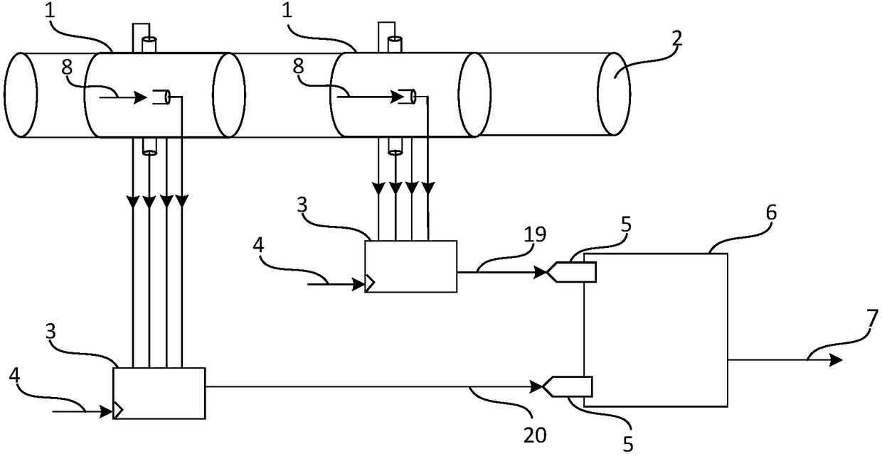
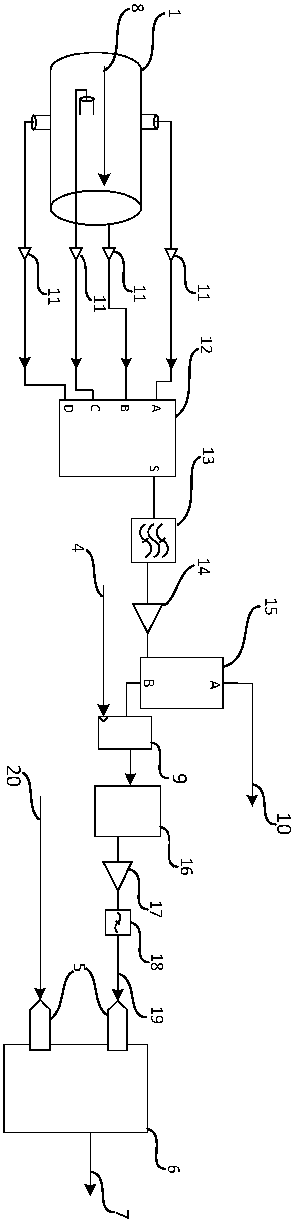
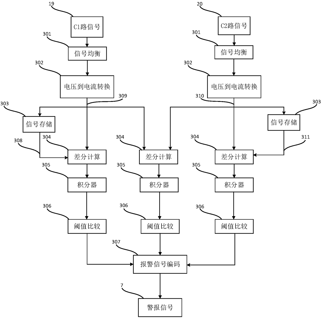
[0018] Such as Figure 1 to 3 As shown, the described beam loss detector device for an ion accelerator is characterized by comprising two beam position probes 1, which are arranged at intervals on the cluster vacuum pipe 2 and are located upstream and downstream, respectively. The stream position probe 1 is respectively connected to the respective front-end processing circuit 3 and driven by the trigger signal 4. The front-end processing circuit 3 is connected to the high-speed sampling digital circuit board 6 through the analog-to-digital conversion circuit 5, and there are a pair of beam position probes at upstream and downstream. The particle bunch 8 obtains the synchronization signal and generates the digital signal to be processed through the high-speed sampling digital circuit board 6. When the difference between the signal and its historical data exceeds a certain thresh...


PUM


Abstract

The invention relates to the technical field of beam loss monitoring of ion accelerators in the technical field of nuclear electronics, and more particularly to a beam loss detector device for an ionaccelerator. The beam loss detector device comprises upstream and downstream beam position probes arranged on a vacuum tube at intervals, wherein the two beam position probes are connected to a clocktrigger through a front-end circuit; the clock trigger is connected with a high-speed sampling digital circuit board via an analog-to-digital conversion circuit; the upstream and downstream beam position probes acquire the synchronization signal of a particle beam and the high-speed sampling digital circuit board generates a digital signal to be processed. When a difference between the signal andits historical data exceeds a certain threshold or a difference between the upstream and downstream signals exceeds a certain threshold, an alarm signal output is generated. The differential beam intensity loss detection system using the beam position probes has a short response time, does not require a compensation circuit, and achieves high measurement accuracy through reasonable design.

Description

Technical field [0001] The present invention relates to the technical field of beam loss monitoring of ion accelerators in the technical field of nuclear electronics, and in particular to a beam loss detector device for ion accelerators. Background technique [0002] Efficient beam loss monitoring plays a vital role in the stable operation of high-current linear accelerators. As an important part of machine protection, there are three main methods for monitoring beam loss in commonly used ion accelerators: Based on gas ionization Room or scintillator photomultiplier tube method, differential beam intensity detection method, and non-intercepting beam damage detection loop. [0003] The gas ionization chamber type beam loss equipment uses the gas sealed inside the instrument and the ionization of various incident particles (γ-rays / protons / heavy particles, etc.) to generate electrical signals to detect beam loss. When the high-energy ion beam passes through the superconducting accele...

Claims


Application Information

Patent Timeline
IPC IPC(8): G01T1/29
CPCG01T1/29
Inventor 谢在鹏何源王志军
Owner INST OF MODERN PHYSICS CHINESE ACADEMY OF SCI
Why Eureka
Try Eureka