Optical imaging element and manufacturing method thereof

An optical imaging and manufacturing method technology, applied in optical components, optics, instruments, etc., can solve the problems of high production cost of optical imaging components, inability to mass-produce at low prices, complex production processes, etc., and achieve low-cost mass production and production. The effect of low cost and simple production process

Pending Publication Date: 2018-07-24
XIANGHANG SHANGHAI TECH CO LTD
View PDF3 Cites 22 Cited by
  • Summary
  • Abstract
  • Description
  • Claims
  • Application Information

AI Technical Summary

Problems solved by technology

The optical imaging elements in the prior art are manufactured by evaporating metal reflective surfaces on the surface of optical plates such as transparent synthetic resin plates or glass plates. This manufacturing method in the prior art requires a special evaporation device...

Method used


Image

  • Optical imaging element and manufacturing method thereof
  • Optical imaging element and manufacturing method thereof
  • Optical imaging element and manufacturing method thereof

Examples


Embodiment Construction

[0025] The present invention will be described in detail below in conjunction with the accompanying drawings and specific embodiments.

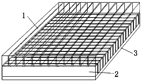
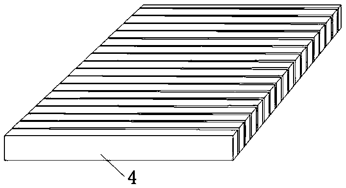
[0026] like Figure 1 to Figure 11 As shown, an optical imaging element, the optical imaging element is mainly composed of an upper transparent laminated body 1 and a lower transparent laminated body 2, the upper transparent laminated body 1 and the lower transparent laminated body 2 are composed of several strips The slender transparent strip 4 of the single-sided or double-sided metal reflective layer 5 is glued together, and the slender transparent strip 4 between the upper light-transmitting laminate 1 and the lower light-transmitting laminate 2 is vertically arranged, and the two light-transmitting laminates The direction of the internal reflection surface of the inner reflection surface forms an orthogonal arrangement, and the upper layer of transparent laminated body 1 and the lower layer of transparent laminated body 2 are bonded toge...


PUM

PropertyMeasurementUnit
Widthaaaaaaaaaa
Heightaaaaaaaaaa

Abstract

The present invention discloses an optical imaging element and a manufacturing method thereof. The optical imaging element is mainly formed by an upper layer of a light transmission stacked body and alower layer of a light transmission stacked body which are formed by binding of a plurality of long and thin transparent bars plated with single-sided or both-sided metal reflection layers, directions of the internal reflection surfaces of the two light transmission stacked bodies form an orthogonal array, and the upper layer of the light transmission stacked body and the lower layer of the lighttransmission stacked body are glued through a transparent macromolecule adhesive. The manufacturing method comprises the steps of: plating of a metal reflection layer, cutting of transparent materials, bonding of the long and thin transparent bars, forming and polishing of the light transmission stacked bodies and forming of the optical imaging element. The optical imaging element is simple in structure and has a good optical imaging performance, the manufacturing method of the optical imaging element is simple in production process and low in production cost, and compared to a manufacturingmethod in the prior art, a lot of manpower and material resources can be saved, and low-cost batch production of optical elements can be achieved.

Description

technical field [0001] The invention belongs to the technical field of optical imaging, and in particular relates to an optical imaging element and a manufacturing method of the optical imaging element. Background technique [0002] The optical imaging element is the basic unit of the optical system, and most of the optical imaging elements play the role of imaging, such as lenses, prisms or mirrors. In addition, there are some optical imaging components that play special roles in the optical system, such as light splitting, image transmission and filtering, such as reticles, filters, gratings or optical fiber components. Holographic lenses, gradient index lenses, and binary optical elements are new optical imaging elements that have emerged in the past ten or twenty years. The optical imaging elements in the prior art are manufactured by evaporating metal reflective surfaces on the surface of optical plates such as transparent synthetic resin plates or glass plates. This m...

Claims


Application Information

Patent Timeline
IPC IPC(8): G02B5/00
CPCG02B5/00
Inventor 王侃张兵
Owner XIANGHANG SHANGHAI TECH CO LTD
Why Eureka
Try Eureka