
Rapid gas-liquid separation device for separating gas from liquid

A technology for separating gas and a separation device, which is applied in the field of rapid gas-liquid separation devices, can solve problems such as difficulties, slow separation, and incomplete separation, and achieve good results, fast gas-liquid separation speed, and improved gas-liquid separation effect

Active Publication Date: 2018-07-27
ZHEJIANG UNIV
View PDF4 Cites 3 Cited by
  • Summary
  • Abstract
  • Description
  • Claims
  • Application Information

AI Technical Summary

Problems solved by technology

However, in current engineering applications, gas-liquid separation devices have different shortcomings. Some of the current separation methods are incomplete, such as baffle separation; some separation is slow, such as gravity sedimentation, etc.
In practice, it is difficult to separate gases from liquids at high flow rates

Method used


Image

  • Rapid gas-liquid separation device for separating gas from liquid
  • Rapid gas-liquid separation device for separating gas from liquid
  • Rapid gas-liquid separation device for separating gas from liquid

Examples


Embodiment 1

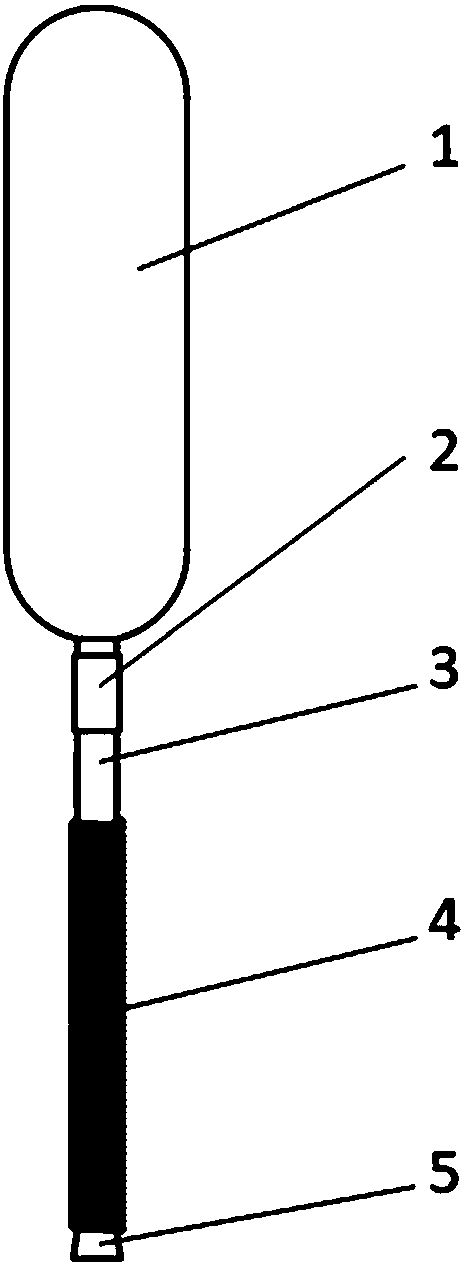
[0035] Such as figure 1 As shown, the device includes a gas storage chamber 1, a sealing ring 2, a plug 5, an air outlet pipe 3 and a gas-liquid separation core 4, the gas-liquid separation core 4 is immersed in the liquid, and one end of the gas-liquid separation core 4 is connected to the outlet One end of the air pipe 3 is connected, the other end of the gas-liquid separation core 4 is blocked with a plug 5 , and the other end of the air outlet pipe 3 is connected to the gas storage chamber 1 through the sealing ring 2 .

[0036] If the gas-liquid separation device of the present invention needs to be installed in the fluid pipeline and protrude from the side wall of the pipeline, the outlet pipe 3 needs to be passed through the pipe wall and sealed with the sealing ring 2 to ensure tightness and no leakage. If it is not necessary to lead out from the side wall of the pipeline, but only protrudes from the liquid surface, the sealing ring 2 is not needed for sealing.

[003...

Embodiment 2

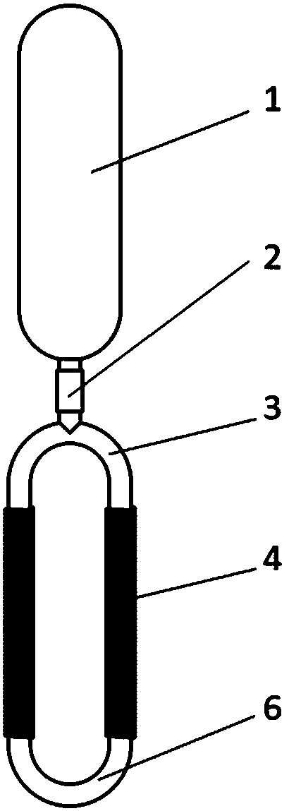
[0044] Such as figure 2 As shown, the device includes a gas storage chamber 1, a sealing ring 2, a connecting pipe 6, an air outlet pipe 3 and two gas-liquid separation cores 4, both of which are immersed in the liquid, and the two gas-liquid separation One end of the core body 4 is connected to both ends of the outlet pipe 3 of the same tee, the other ends of the two gas-liquid separation cores 4 are connected with a U-shaped connecting pipe 6, and the third end of the outlet pipe 3 passes through the sealing ring 2 It is connected with the gas storage chamber 1.

[0045]If the gas-liquid separation device of the present invention needs to be installed in the fluid pipeline and protrude from the side wall of the pipeline, the outlet pipe 3 needs to be passed through the pipe wall and sealed with the sealing ring 2 to ensure tightness and no leakage. If it is not necessary to lead out from the side wall of the pipeline, but only protrudes from the liquid surface, the sealing...


PUM

PropertyMeasurementUnit
Diameteraaaaaaaaaa
Gapaaaaaaaaaa

Abstract

The invention discloses a rapid gas-liquid separation device for separating gas from a liquid. At least one gas-liquid separation core is soaked in the liquid, and each gas-liquid separation core is of a net barrel type or spring type structure and is covered with a superhydrophobic material coating on the surface. Each gas-liquid separation core adopts an independent structure, and a gas-liquid separation core array can be formed by combining gas-liquid separation cores through connecting pipelines. By means of the superhydrophobic characteristic of the superhydrophobic material, a solid-gas-liquid three-phase interface is formed on the peripheral wall of each net barrel type or spring type gas-liquid separation core, gas is gathered in each gas-liquid separation core, the liquid is isolated outside each gas-liquid separation core, peripheral gas is rapidly separated from the liquid when making contact with the surface of each gas-liquid separation core, and the gas-liquid separationefficiency of gas in the liquid is improved.

Description

technical field [0001] The invention relates to chemical, food, hydraulic, medical, biological, papermaking and other industrial fields, in particular to a gas-liquid rapid separation device for separating gas from liquid, as a gas separator in liquid. Background technique [0002] Separation of liquid and gas is the process of separating gas from liquid or liquid from gas to obtain pure liquid or pure gas by physical and chemical means, which belongs to the process of fluid separation. Common gas-liquid separation methods include gravity sedimentation, baffle separation, centrifugal force separation, screen separation, ultrafiltration separation and packing separation. However, in current engineering applications, gas-liquid separation devices have different disadvantages. Some of the current separation methods are incomplete, such as baffle separation; some separation is slow, such as gravity sedimentation. Separating gases from liquids at high flow rates is difficult in ...

Claims


Application Information

Patent Timeline
IPC IPC(8): B01D19/00
CPCB01D19/0005
Inventor 邹俊李博吉晨
Owner ZHEJIANG UNIV
Learn More