High-density plate derusting device

A high-density, plate technology, used in grinding drive devices, devices for coating liquid on surfaces, grinding slides, etc. Oxidation degree and other problems, to achieve the effect of convenient operation and simple structure

Inactive Publication Date: 2018-07-27
广州正顺机械技术开发有限公司
View PDF3 Cites 0 Cited by
  • Summary
  • Abstract
  • Description
  • Claims
  • Application Information

AI Technical Summary

Problems solved by technology

[0002] With the continuous development of industrial technology, some high-density metal sheets are used more and more widely. However, during the production and processing of these high-density metal sheets, the outer surface often needs to be polished and painted to increase the thickness of the sheet. For the aesthetics and oxidation resistance of the outer surface, traditionally, it is generally necessary to purchase a grinding device and a painting device separately. The rust on the outer surface of the plate is polished by the grinding device, and then the plate is moved to the painting device after polishing. It needs to increase the cost of equipment procurement, increase the workload of manpower, and reduce the work efficiency of sheet metal processing

Method used


Image

  • High-density plate derusting device
  • High-density plate derusting device
  • High-density plate derusting device

Examples


Embodiment Construction

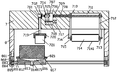
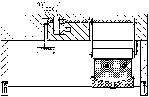
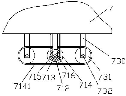
[0014] Such as Figure 1-4 As shown, a high-density plate derusting device of the present invention includes left and right base frames 8 that are installed on the bottom end face of the mounting plate 7, and the two outer end faces of the base frame 8 are provided with hand-carrying grooves 881. A portable rack 882 is fixed in the portable slot 881, and the portable rack 882 is used to facilitate the mobile handling operation of the device. The inner wall body of the mounting plate 7 is respectively provided with a left transfer slot 702, a middle slot 706, and a right turn slot. The connection groove 711, the sliding connection block 705 is installed in the sliding connection in the middle groove 706, and the first screw rod 718 is installed in the sliding connection block 705, and the left side of the first screw rod 718 is elongated at the end It is rotatably connected with the inner wall on the left side of the middle groove 706, and the extended end of the right side of ...


PUM


Abstract

The invention discloses a high-density plate derusting device. The high-density plate derusting device comprises base frames which are mounted on the bottom end face of a mounting plate in a bilaterally-symmetrical mode. Handheld grooves are formed in the outer end faces of the two base frames correspondingly. Handheld frames are fixedly arranged in the handheld grooves. A left connection groove,a middle groove and a right connection groove are formed in an inner wall body of the mounting plate. A sliding connection block is mounted in the middle groove in a sliding fit mode. A first spiral rod is mounted in the sliding connection rod in a matched mode. The left extension end of the first spiral rod is connected with the inner wall of the left side of the middle groove in a running fit mode, and the right extension end of the first spiral rod is connected with a first electric rotary motor. The outer surface of the first electric rotary motor is fixedly mounted on the inner wall of the right side of the middle groove. A second electric rotary motor is fixedly mounted in the portion, above the first spiral rod, of the sliding connection block. The left extension end of the second electric rotary motor is connected with a first spline shaft, and the right extension section of the second electric rotary motor is connected with a second spline shaft. The high-density plate derusting device is simple in structure, convenient to operate and capable of reducing the workload of workers.

Description

technical field [0001] The invention relates to the technical field of high-density plate processing, in particular to a high-density plate derusting device. Background technique [0002] With the continuous development of industrial technology, some high-density metal sheets are used more and more widely. However, during the production and processing of these high-density metal sheets, the outer surface often needs to be polished and painted to increase the thickness of the sheet. For the aesthetics and oxidation resistance of the outer surface, traditionally, it is generally necessary to purchase a grinding device and a painting device separately. The rust on the outer surface of the plate is polished by the grinding device, and then the plate is moved to the painting device after polishing. It needs to increase the equipment procurement cost, increase the manual workload, and reduce the work efficiency of sheet metal processing. Contents of the invention [0003] The t...

Claims


Application Information

Patent Timeline
IPC IPC(8): B24B27/033B24B41/06B24B47/12B24B47/16B24B47/22B24B41/02B05C13/02B05C1/08
CPCB24B27/033B05C1/0821B05C13/02B24B41/02B24B41/06B24B47/12B24B47/16B24B47/22
Inventor 邹承针
Owner 广州正顺机械技术开发有限公司
Why Eureka
Try Eureka