Mechanical air pressure expanding shaft used for winding and unwinding system on papermaking and printing packaging equipment

A technology of printing, packaging and pneumatic shaft, which is applied in the field of food machinery, can solve the problems of small gap between the expansion mandrel and the outer tube, cannot fully meet the production requirements, and cannot meet the production requirements, etc., and achieves compact structure and deformation resistance Strong, high-precision effect

Inactive Publication Date: 2018-07-27
安徽哲乐机电有限公司
View PDF0 Cites 4 Cited by
  • Summary
  • Abstract
  • Description
  • Claims
  • Application Information

AI Technical Summary

Problems solved by technology

[0004] At present, the conventional air expansion shaft often fails to meet the production demand during use, and cannot fully meet the produ

Method used


Image

  • Mechanical air pressure expanding shaft used for winding and unwinding system on papermaking and printing packaging equipment
  • Mechanical air pressure expanding shaft used for winding and unwinding system on papermaking and printing packaging equipment
  • Mechanical air pressure expanding shaft used for winding and unwinding system on papermaking and printing packaging equipment

Examples


Embodiment Construction

[0024] The present invention will be further described below in conjunction with the accompanying drawings.

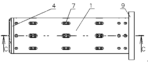
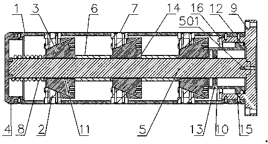
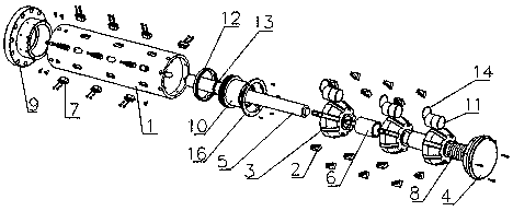
[0025] Such as Figure 1-8 As shown in , a mechanical pneumatic shaft expansion shaft used in papermaking and printing and packaging equipment for winding and unwinding systems includes a mandrel 5, and the boss at one end of the mandrel 5 is inserted into the circular groove of the flange 9, The outer casing of the flange 9 is connected to one end of the shaft tube 1, the inner casing of the flange 9 is fitted with a thrust piston 10, the thrust piston 10 is fitted with a sealing cover 16, and is fixed to the end of the flange 9 by bolts, and the thrust piston 10 is also provided with a guide belt 15 at the contact point with the inner wall of the tube platform of the flange 9, and a plurality of flower discs 3 are sequentially socketed on the mandrel 5 through the oiling copper sleeve 11, and spacers 6 are sleeved on the mandrel 5 between the flower discs 3, and the ...


PUM


Abstract

The invention discloses a mechanical air pressure expanding shaft used for a winding and unwinding system on papermaking and printing packaging equipment. The mechanical air pressure expanding shaft comprises a core shaft body; a boss at one end of the core shaft body is inserted into a round groove of a flange; a cylindrical stand of the flange is sleeved with one end of a shaft pipe; a thrust piston is sleeved with the cylindrical stand of the flange, sleeved with a sealing cover and fixedly connected to the end of the cylindrical stand of the flange through bolts; guiding bands are furtherdisposed in the contact position of the thrust piston and the inner wall of the cylindrical stand of the flange; the core shaft body is sequentially sleeved with a plurality of disc chucks through oiling copper sleeves; the portions, between the disc chucks, of the core shaft body are sleeved with spacer bushes; the portions, at the tail ends of the disc chucks, of the core shaft body are sleevedwith springs; a boss at the other end of the core shaft body is arranged in an inner round groove of an end socket in a sleeved mode; and an outer round ring of the end socket is arranged in the otherend of the shaft pipe in a sleeved mode and connected through screws. The mechanical air pressure expanding shaft used for the winding and unwinding system on the papermaking and printing packaging equipment is compact in structure, novel in idea, large in working stroke and bearing capacity, long in service life, easy to maintain and convenient to repair; and the using accuracy is high, a shaftbody is made of a seamless steel tube, and therefore the non-deformability is high.

Description

technical field [0001] The invention relates to the technical field of food machinery, in particular to a mechanical air pressure shaft expansion shaft used in the winding and unwinding systems of papermaking and printing and packaging equipment. Background technique [0002] The air shaft is a special winding and unwinding shaft, that is, the shaft whose surface can protrude after high-pressure inflation, and the shaft whose surface part retracts quickly after deflation is called the air shaft. [0003] The air shaft and air sleeve are extremely convenient and quick to use. You only need to prepare your own air source, and the air pressure is controlled within the range of 6-8kg / cm2. ), as long as the air gun is inflated against the air nozzle on the air expansion shaft, it can withstand the external parts (such as a round paper tube), and when it is necessary to loosen the paper and unload, press the sliding outer part on the air nozzle with your hand Parts (such as round...

Claims


Application Information

Patent Timeline
IPC IPC(8): B65H75/24
CPCB65H75/243B65H2701/50
Inventor 乔印保刘阳
Owner 安徽哲乐机电有限公司
Why Eureka
Try Eureka