Pier protection device for bridge in debris flow channel and design method

A technology of protective devices and design methods, applied in bridge construction, road safety devices, bridges, etc., can solve the problems of unfavorable long-term use, abrasion of bridge pier building materials, high maintenance and replacement costs, and achieve low potential risks, low production and maintenance costs, and high maintenance costs. good protection effect

Active Publication Date: 2018-07-27
CHONGQING JIAOTONG UNIVERSITY
View PDF6 Cites 11 Cited by
  • Summary
  • Abstract
  • Description
  • Claims
  • Application Information

AI Technical Summary

Problems solved by technology

The essence of this device is to add a protective buffer layer on the water-facing surface of the concrete pier. The main shortcomings are: 1. Although the protective buffer layer can reduce the impact of debris flow on the pier, when the debris fluid containing a large amount of coarse particles flows from the side of the pier, There is an obvious abrasion problem of debris fluid on pier building materials, which is unfavorable for long-term use
2. The protective buffer layer is integrated with the pier design, and the maintenance and replacement costs are high

Method used


Image

  • Pier protection device for bridge in debris flow channel and design method
  • Pier protection device for bridge in debris flow channel and design method
  • Pier protection device for bridge in debris flow channel and design method

Examples


Embodiment 1

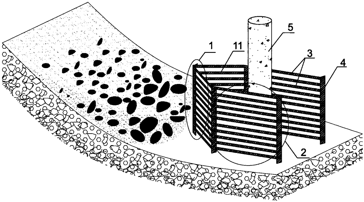
[0053] Such as Figure 1 ~ Figure 4 Shown, design debris flow ditch bridge pier protection device of the present invention.

[0054] The background investigation of debris flow ditches, combined with the on-site investigation of debris flow ditches and the historical record data of debris flow, determined: the maximum particle size of debris flow d max = 2m, debris flow velocity u = 8m / s, debris flow depth h = 6m, debris flow channel width at bridge pier W = 30m, bridge pier width b = 2m, debris flow impact on bridge pier F = 550kN, bridge pier can withstand the maximum impact force F 抗 = 330kN.

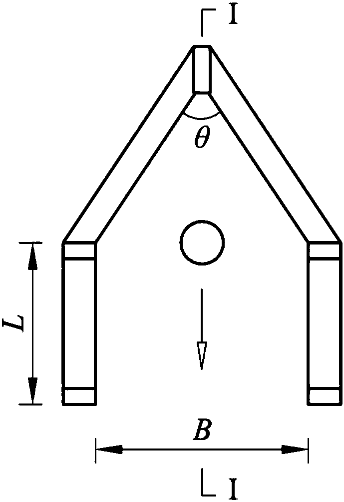
[0055] Design angle θ=60° for water-facing tip 1.

[0056] figure 1 It is a schematic diagram of the protection device for the bridge pier of the debris flow channel. The pier protection device of the debris flow ditch is fixed in the ditch by the column 4; it is a semi-surrounding structure surrounding the pier 5; The direction of the ditch extends backwards to form a side rail...


PUM


Abstract

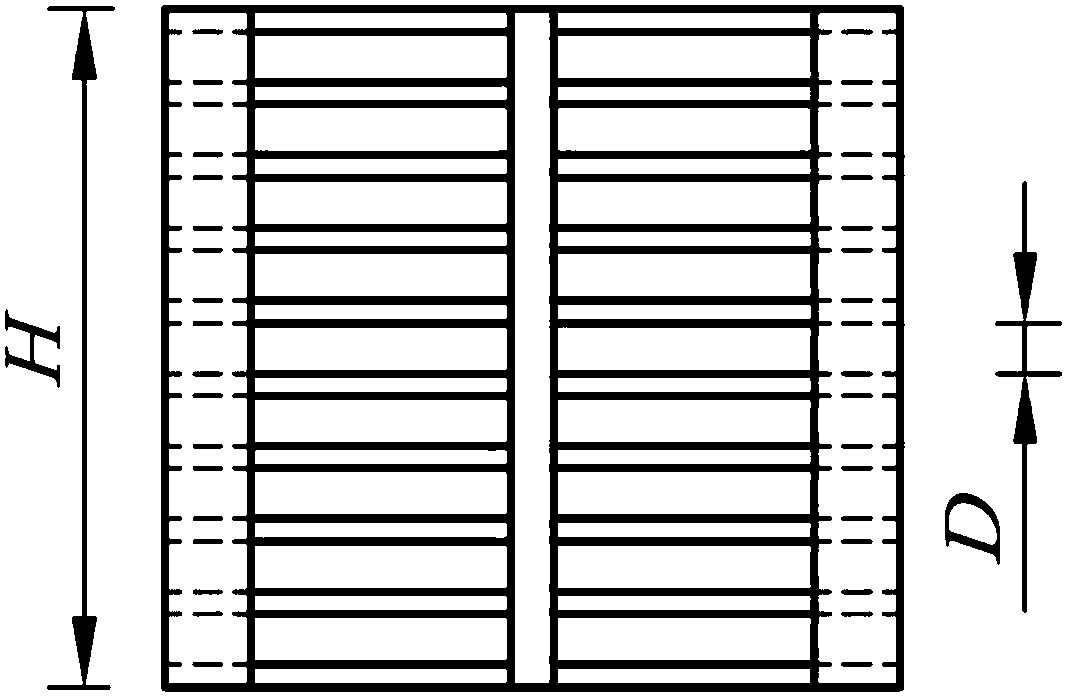
The invention discloses a pier protection device for a bridge in a debris flow channel. Aiming at the defects that an existing product is unfavorable in long-term use and high in maintenance and replacing cost, the pier protection device is of a semi-enclosing structure enclosing a pier and is fixed in a channel through vertical columns; the front end of the pier protection device serves as a water-coming tip with the included angle being theta, and the tail ends of two water-coming tip bevels of the water-coming tip extend backwards in the channel direction to form side bars; and the pier protection device is of a fence structure with transverse fence bars. The invention further provides a design method of the pier protection device. The design method is used for scientific design of important parameters such as the interval D of the fence bars, the height H of the protection device, the width B of the protection device, and the length L of the side bars. According to a product of thepier protection device, the movement state of debris flow can be changed only in a very small area at a pier, the pier protection device overall has the functions of protection of trapping coarse sand and discharging fine sand and homeopathic dredging, and secondary hazards are prevented; the product is concise in structure, convenient to mount, low in production and maintenance cost and capableof being used for a long term; and the matched design method is scientific and reasonable.

Description

technical field [0001] The invention relates to a protection device and a design method, in particular to a protection device for debris flow ditch bridge piers and a design method thereof, belonging to the technical fields of civil engineering and geological disaster prevention and control. Background technique [0002] Debris flow is a solid-liquid two-phase fluid full of sediment and stones that occurs in mountainous areas. It usually has the characteristics of sudden outbreak, short duration, high content of solid phase substances, wide gradation, and strong scouring and silting ability. The damage of debris flow to the bridges built on the ditch is mainly reflected in two aspects: one is to silt and submerge bridges, reducing their service life; the other is to wash away bridge piers and abutments, which directly leads to structural damage. [0003] The Chinese utility model patent with the authorized announcement number CN 202347498U discloses a bridge pier protection...

Claims


Application Information

Patent Timeline
Patent Type & Authority Applications(China)
IPC IPC(8): E01F15/14E01D19/02G06F17/50
CPCE01D19/02E01F15/141G06F30/13
Inventor 谢涛陈洪凯周佺
Owner CHONGQING JIAOTONG UNIVERSITY
Why Eureka
Try Eureka