Supercharge Your Innovation With Domain-Expert AI Agents!

Power generation device based on liquid thermal energy conversion

A technology for thermal energy conversion and power generation devices, which is applied in steam engine devices, machines/engines, steam applications, etc., and can solve the problems of low thermal efficiency, high energy consumption, and low efficiency in nuclear power plants.

Inactive Publication Date: 2018-07-27
李万奎
View PDF0 Cites 0 Cited by
  • Summary
  • Abstract
  • Description
  • Claims
  • Application Information

AI Technical Summary

Problems solved by technology

Hydropower generation has high requirements on the geographical environment, requiring a specific large amount of water and high drop, and cannot be used in arid areas; thermal power generation has high pollution, high energy consumption, low efficiency, and dim prospects for sustainable development; nuclear power plants have low thermal efficiency, so they are relatively Generally, fossil fuel power plants discharge more waste heat into the environment, causing serious heat pollution; tidal power generation works when the tide rises and falls every day, and solar power generation can only be used when the sun is shining during the day, both of which have the problem of intermittent output

Method used


Image

  • Power generation device based on liquid thermal energy conversion
  • Power generation device based on liquid thermal energy conversion

Examples


Embodiment 1

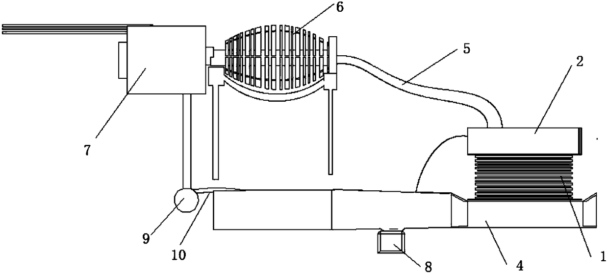
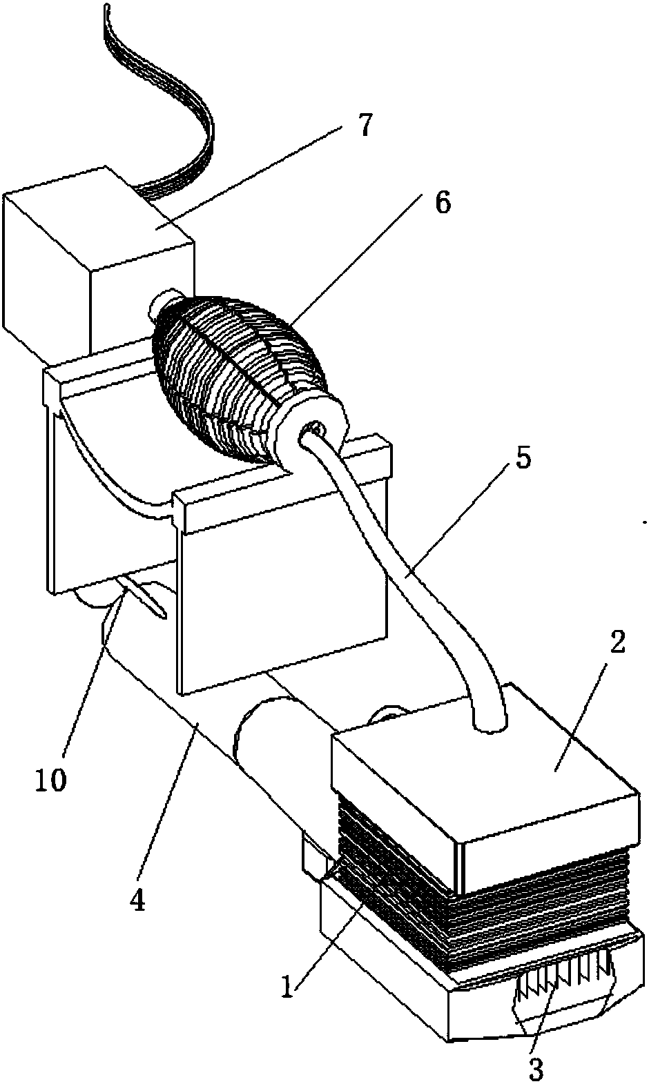
[0024] Embodiment 1, see attached figure 1 , 2 , a power generation device based on liquid thermal energy conversion, which includes: a steam turbine engine 6, a generator 7, a heat pump body 1, a steam generator 2 and a water pipe 4;

[0025] The heat pump body 1 is composed of superimposed temperature difference sheets, and a heat transfer sheet 3 is provided between adjacent temperature difference sheets and at the bottom of the bottom temperature difference sheet; the heat pump body 1 is divided into a lower cooling end and an upper heating end;

[0026] The water pipe 4 is provided with an opening, and the bottom end of the heat pump body 1 extends into the water pipe 4 from the opening. touch;

[0027] The steam generator 2 is a metal box, which is filled with pure water; the heating end of the heat pump body 1 is in contact with the bottom of the steam generator 2, and is used to heat the pure water in the steam generator 2 to vaporize it; the steam generator 2 Conne...

Embodiment 2

[0033] Embodiment 2, on the basis of Embodiment 1, specific limitations are made to the heat transfer sheet 3, the heat pump body 1, the steam generator 2 and the water conduit 4;

[0034] The heat transfer sheet 3 is a copper sheet with good thermal conductivity, the thickness of the heat transfer sheet 3 between adjacent temperature difference sheets is 10mm, and the thickness of the bottom heat transfer sheet 3 is 100mm or more;

[0035] The size of the steam generator 2 is 9.1×9.1×2m;

[0036] The temperature of the liquid in the water pipe 4 is about 20°C, and the temperature drops to 1-5°C after passing through the cooling end of the heat pump body 1; in order to ensure the heat absorption effect, a flow regulating valve is installed on the water pipe 4 to adjust the flow rate. The opening of the valve can control the flow of liquid in the water pipe 4, thereby ensuring the transfer of heat;

[0037] The heat pump body 1 is composed of nine 9×9-meter temperature differe...


PUM


Abstract

The invention relates to the technical field of energy utilization, in particular to a power generation device. The power generation device based on liquid thermal energy conversion comprises a steamturbine engine, a power generator, a heat pump, a steam generator and a water pipeline. The heat pump is composed of overlapped thermoelectric sheets. Heat transfer sheets are arranged between the adjacent thermoelectric sheets and at the bottoms of the thermoelectric sheets on the lowest layer. The heat pump comprises a refrigerating end on the lower portion and a heating end on the upper portion. The heat transfer sheets on the lowest layer of the heat pump are located in the water pipeline and make contact with liquid in the water pipeline. The heating end of the heat pump makes contact with the bottom of the steam generator. The steam generator is connected with the steam turbine engine through a steam pipeline. On the one hand, the steam turbine engine is connected with the power generator through a shaft, and on the other hand, the steam turbine engine is connected with a buffer tank through a pipeline. The buffer tank is connected with a water tank through a connecting pipe. Themiddle section of the connecting pipe is located in the water pipeline. The water tank communicates with the steam generator. The power generation device is in accordance with the energy conservationlaw, energy is saved, and the environment is protected.

Description

technical field [0001] The invention relates to the technical field of energy utilization, in particular to a power generation device. Background technique [0002] Existing power generation technologies include: hydroelectric power generation, nuclear power generation, thermal power generation, tidal power generation, and solar power generation, each of which has its own limitations in use. Hydropower generation has high requirements on the geographical environment, requiring a specific large amount of water and high drop, and cannot be used in arid areas; thermal power generation has high pollution, high energy consumption, low efficiency, and dim prospects for sustainable development; nuclear power plants have low thermal efficiency, so they are relatively Generally, fossil fuel power plants discharge more waste heat into the environment, causing serious thermal pollution; tidal power generation works when the tide rises and falls every day, and solar power generation can...

Claims


Application Information

Patent Timeline
Patent Type & Authority Applications(China)
IPC IPC(8): F01K13/00F01K17/02F01K19/00F01D15/10
CPCF01K13/00F01D15/10F01K17/02F01K19/00
Inventor 李万奎
Owner 李万奎
Features
  • R&D
  • Intellectual Property
  • Life Sciences
  • Materials
  • Tech Scout
  • Unparalleled Data Quality
  • Higher Quality Content
  • 60% Fewer Hallucinations
Learn More