Eureka AIR delivers breakthrough ideas for toughest innovation challenges, trusted by R&D personnel around the world.

Power splitting tension loading test equipment suitable for CT scan

A technology of loading test and CT scanning, applied in the direction of applying stable tension/pressure to test the strength of materials, measuring devices, instruments, etc., can solve the problems of introducing CT scanning instruments, to ensure the accuracy of load control and solve the problem of excessive spatial scale Small, low friction effect

Active Publication Date: 2018-07-27
HOHAI UNIV
View PDF11 Cites 2 Cited by
  • Summary
  • Abstract
  • Description
  • Claims
  • Application Information

AI Technical Summary

Problems solved by technology

[0005] Due to the limitations of the loading equipment for the split tensile test and medical X-ray CT scanning equipment, it is impossible to introduce CT scanning equipment on the loading equipment for the split tensile test at this stage

Method used


Image

  • Power splitting tension loading test equipment suitable for CT scan
  • Power splitting tension loading test equipment suitable for CT scan
  • Power splitting tension loading test equipment suitable for CT scan

Examples


Embodiment 1

[0025] Embodiment 1 A description of the structure of a dynamic split-pull loading test device suitable for CT scanning according to the present invention

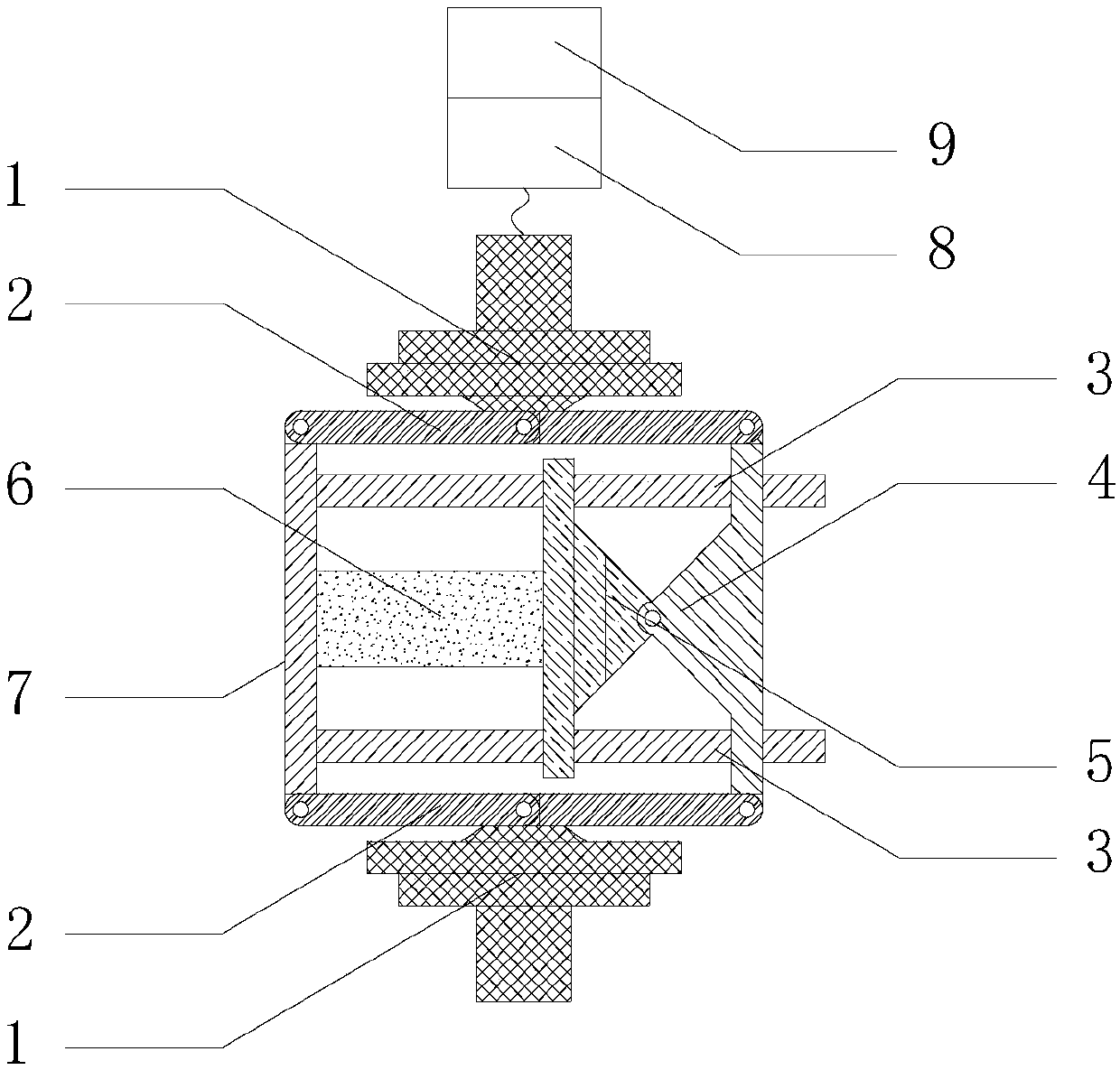
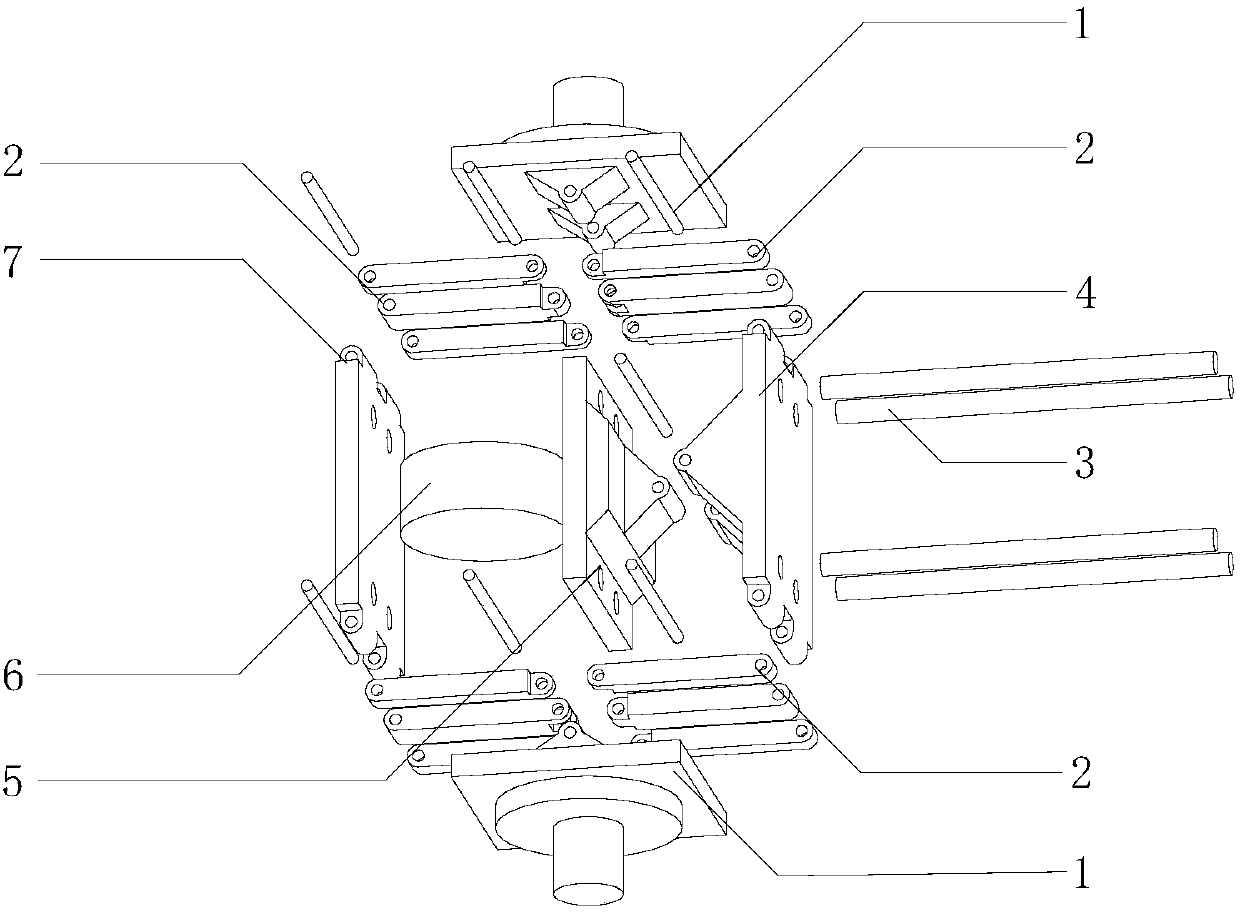
[0026] Such as figure 1 , figure 2 As shown, a dynamic split-pull loading test equipment suitable for CT scanning includes a tension platform 1, a tension-compression conversion mechanism 2, a steel rod 3, a pressure platform (pressing end) 4, a universal head 5, a specimen 6, Constraint platform (fixed end) 7, load and displacement sensor 8, computer control system 9.

[0027] The hydraulic stretcher, pressure and displacement sensors 8 and computer control system 9 connected externally to the tension platform 1 constitute the load application control system of the equipment.

[0028] The tension platform 1 and the pressure platform 4 are connected through the tension-compression conversion mechanism 2, and the tension-compression conversion mechanism 2 transmits the load of the tension platform 1 to the pressure platf...

Embodiment 2

[0034] Embodiment 2 A method of using the dynamic splitting and pulling loading test equipment suitable for CT scanning according to the present invention

[0035] The specific test steps are as follows:

[0036] Step 1, place and adjust the equipment: fix the equipment constraining platform 7 on the bed of the CT scanner, and adjust so that the length direction of the steel rod 3 is parallel to the direction of the scanning section;

[0037] Step 2, installation of the loading and measuring system: connect the hydraulic tensioner to the tension platform 1 at both ends, install the pressure and displacement sensor 8 and connect it to the computer;

[0038] Step 3, setting of experimental parameters: select the control loading mode of the test (load control or displacement control), set the initial parameters (displacement initial parameters x 0 or the initial parameter of the force F 0 , for pre-clamping specimens), incremental parameters (displacement incremental paramete...


PUM


Abstract

The invention provides a piece of power splitting tension loading test equipment suitable for CT scan. The equipment comprises the following components: a pulling force platform, a pulling and pressing converting mechanism, a pressure platform, a universal joint, steel poles, a test piece, a constraint platform, a pressure and displacement sensor, and a computer control system. A test piece is clamped between the constraint platform and the pressure platform; the universal joint guarantees realization of parallel pressurization; the pressure platform and the constraint platform are connected into a reaction frame through the steel poles, in order to form a self-balance system; the pulling force platform and the pressure platform are connected by the pulling and pressing converting mechanism, in order to realize conversion from pulling force load into pressure load; the pulling force platform is externally connected to a hydraulic elongator, in order to carry out application of dynamicloading; the load and displacement sensor, and the computer control system can guarantee loading mode and loading rate of the test, and at the same time experiment data is recorded. The equipment hasa small volume and is convenient for movement, and can be placed in a detection scope of a medical X-ray CT machine, in order to realize synchronization of measurement and loading, and effectively solve the problem of synchronous recording of crack initiation in the splitting tension test process.

Description

technical field [0001] The invention relates to the field of testing the splitting tensile properties of brittle materials in civil engineering materials, in particular to a dynamic splitting and pulling loading test equipment suitable for medical X-ray CT scanners. Background technique [0002] Brittle materials tend to produce brittle fracture after being stretched to generate unstable cracks. This kind of damage will lead to the rapid collapse of buildings, causing huge economic losses, threatening the safety of public life, and also causing an inevitable impact on people's psychology. This requires that the material not only meet the basic mechanical parameters, but also have sufficient tensile properties and toughness. The split-tensile loading test equipment can meet the test of such toughness properties of materials. [0003] However, scholars found that due to the heterogeneity and anisotropy of the material, the crack initiation position, propagation path and fina...

Claims


Application Information

Patent Timeline
Patent Type & Authority Applications(China)
IPC IPC(8): G01N3/08
CPCG01N3/08G01N2203/0062G01N2203/0085G01N2203/0647
Inventor 张华郑凯王雷王悦李启亮戚亚珍杨健
Owner HOHAI UNIV
Why Eureka
Eureka Blog
Learn More