Wire winding type metal oxide film resistor and processing process

A processing technology and oxide film technology, applied in the direction of non-adjustable metal resistors, resistors, resistor sets, etc., can solve the problems of bursting, blown, no resistance wire, etc., to enhance the use and operation safety and power expansion. Effect

Pending Publication Date: 2018-07-27
东莞市创嘉电子有限公司
View PDF3 Cites 4 Cited by
  • Summary
  • Abstract
  • Description
  • Claims
  • Application Information

AI Technical Summary

Problems solved by technology

[0003] The above-mentioned power resistor has a fatal shortcoming: once there is overcurrent, that is, when the voltage applied to both ends of the resistor exceeds the rated value by a large amount, the middle part of the resistor will have worse heat dissipation than the two ends, and the resistance wire at this time becomes The heating wire will burn red, and the ceramic rod will burst and break under the condition of local intense heating. The resistance wire has no support and heat conductor, and will burn out if it heats up further; so an "explosion scene" is formed around the resistor. ", will endanger the safety of other electronic components, which is the drawback that people hope to overcome
[0010] However, the patent of the present invention is faced with the problem of how to prevent explosion after the low-resistance resistance below several ohms is blown by a large current.
[0011] Therefore, this patented technical solution has no reference significance for solving the problem of "how to realize the non-explosion problem after the low-resistance resistor is blown by a large current"

Method used


Image

  • Wire winding type metal oxide film resistor and processing process
  • Wire winding type metal oxide film resistor and processing process
  • Wire winding type metal oxide film resistor and processing process

Examples


Embodiment Construction

[0042] The present invention will be described below in conjunction with the first specific embodiment.

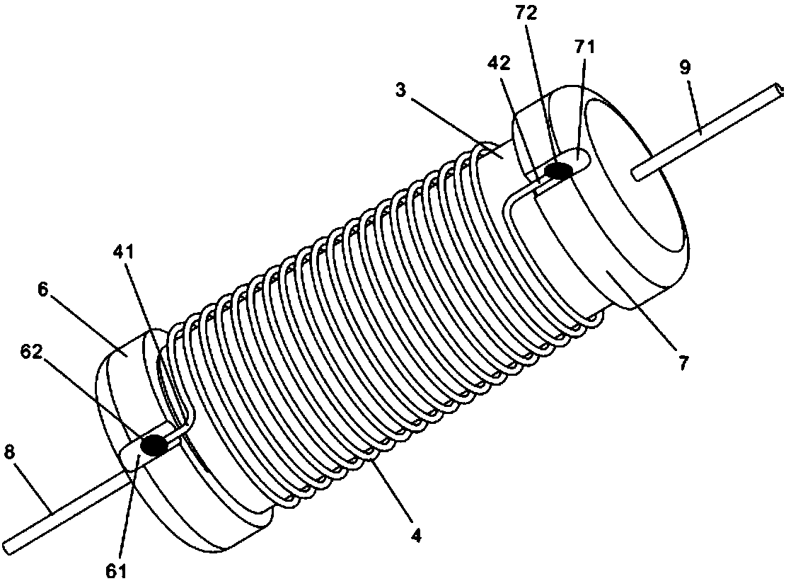
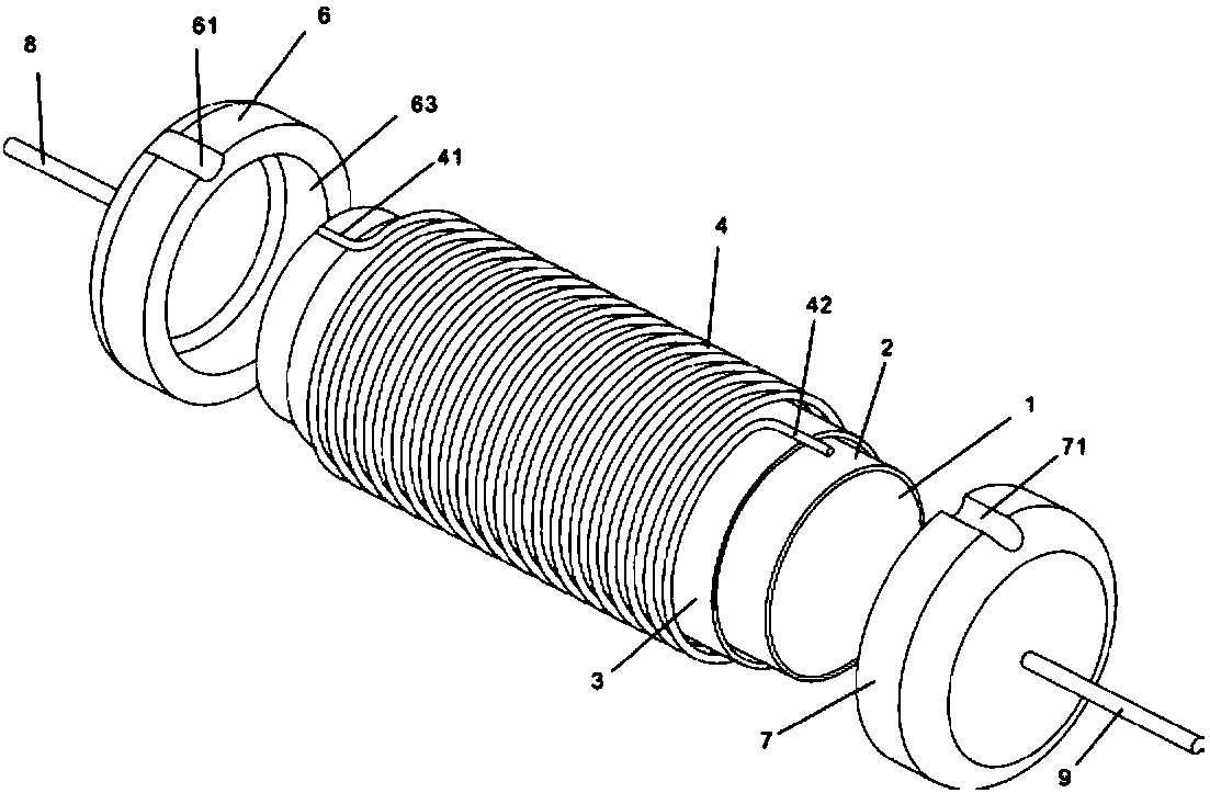
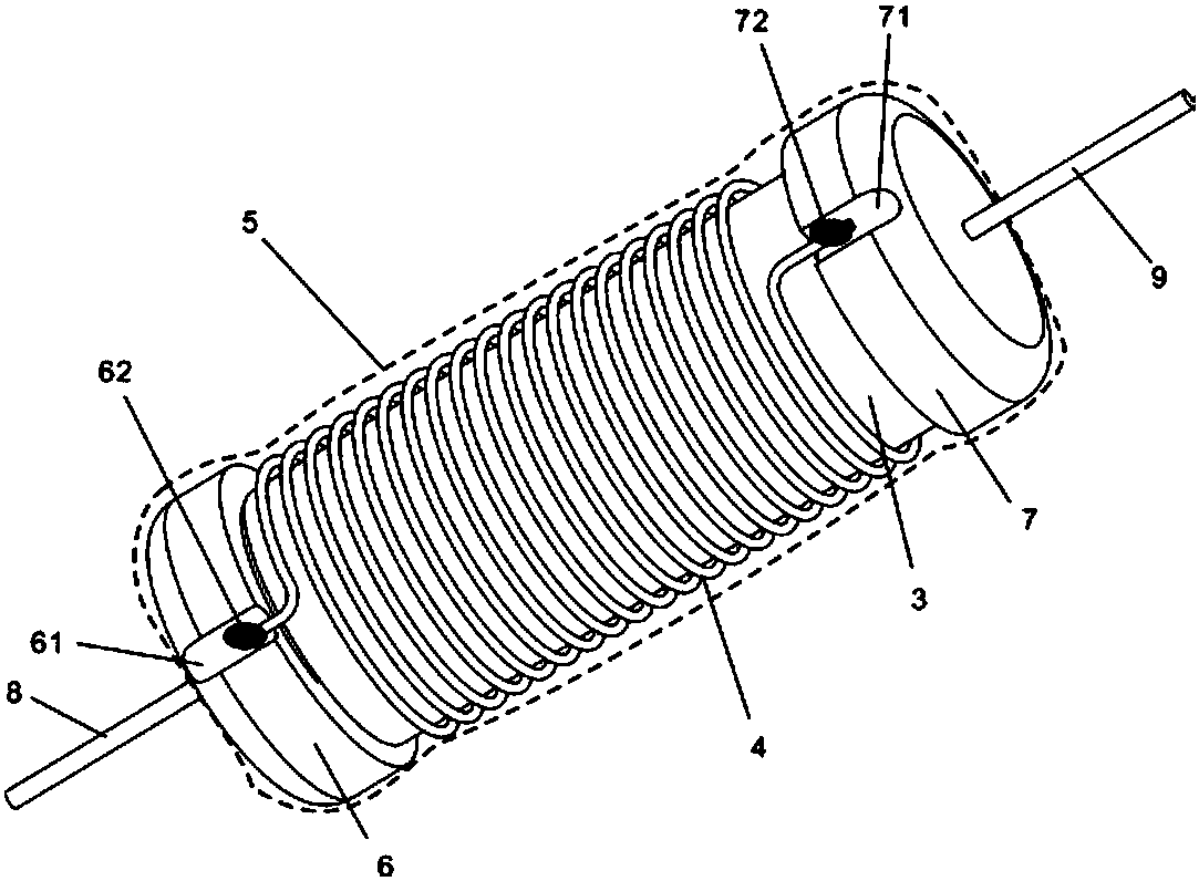
[0043] Such as Figure 1 to Figure 5 As shown, implement a wire-wound metal oxide film resistor and its processing technology;

[0044] The resistor comprises: a metal oxide film resistance layer 2 coated on the peripheral surface of a ceramic core 1, an insulating layer 3 is coated on the metal oxide film resistance layer 2, and a resistance wire 4 is wound outside the insulating layer 3;

[0045] In the area where the two ends of the metal oxide film resistance layer 2 are not coated with the insulating layer 3, the left metal end cap 6 and the right metal end cap 7 are inserted respectively, so that the left inner wall 63 of the left metal end cap 6 is in contact with the metal oxide film resistance layer. 2. Close contact and good conduction; the right inner wall of the right metal end cap 7 is in close contact with the metal oxide film resistance layer 2 and good con...


PUM

PropertyMeasurementUnit
thicknessaaaaaaaaaa
electrical resistanceaaaaaaaaaa

Abstract

The invention discloses a wire winding type metal oxide film resistor and a processing process. The wire winding type metal oxide film resistor is characterized in that the circumferential surface ofa ceramic core is coated with a metal oxide film resistance layer, the metal oxide film resistance layer is coated with an insulating layer, and a resistance wire winds the insulating layer; after theleft tip and left metal end cap of the resistance wire are welded at a left welding point and the right tip and right metal end cap of the resistance wire are welded at a right welding point, and theouter surfaces of the resistance wire, the left metal end cap and the right metal end cap are coated with an insulating wrapping layer. The wire winding type metal oxide film resistor and the processing process have the advantages that the power of the resistor is doubled as compared with that of a traditional wire winding type resistor which is identical with the resistor in volume; when the resistor meets with severe current overrun, the resistor only has disconnection when a resistor medium is burnt out due to the triple wrapping of the metal oxide film resistance layer, the insulating layer and the resistance wire, severe explosion can be avoided, damage to other devices is avoided, a space environment on a circuit board can be prevented from being polluted, and use and operation safety is enhanced greatly.

Description

technical field [0001] The invention relates to the manufacturing technology of electronic components, in particular to the manufacturing technology of resistors, especially wire-wound metal oxide film resistors and their processing technology. Background technique [0002] In the prior art, resistors with higher power are mostly wirewound resistors, that is, resistor wires are wound on pure ceramic rods and then packaged. [0003] The above-mentioned power resistor has a fatal shortcoming: once there is overcurrent, that is, when the voltage applied to both ends of the resistor exceeds the rated value by a large amount, the middle part of the resistor will have worse heat dissipation than the two ends, and the resistance wire at this time becomes The heating wire will burn red, and the ceramic rod will burst and break under the condition of local intense heating. The resistance wire has no support and heat conductor, and will burn out if it heats up further; so an "explosio...

Claims


Application Information

Patent Timeline
Patent Type & Authority Applications(China)
IPC IPC(8): H01C1/034H01C1/036H01C1/144H01C1/148H01C1/16H01C3/20H01C7/00H01C17/00
CPCH01C1/16H01C1/034H01C1/036H01C1/144H01C1/148H01C3/20H01C7/001H01C17/00
Inventor 帅冬生
Owner 东莞市创嘉电子有限公司
Why Eureka
Try Eureka