
Planar transformer, electronic equipment and production method of planar transformer

A planar transformer, alpha technology, applied in the direction of transformer/inductor coil/winding/connection, transformer/inductor components, inductor/transformer/magnet manufacturing, etc., can solve the problem of many primary/secondary coil layers, planar transformer Problems such as low power density and large proximity effect

Inactive Publication Date: 2018-07-27
UTT ELECTRONICS SZ CO LTD
View PDF2 Cites 9 Cited by
  • Summary
  • Abstract
  • Description
  • Claims
  • Application Information

AI Technical Summary

Problems solved by technology

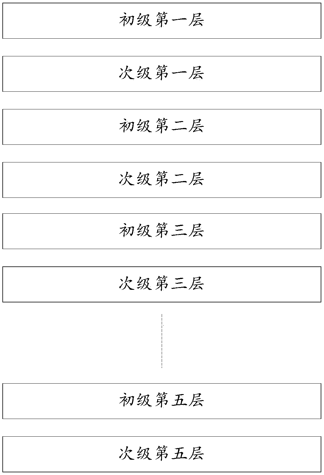
[0003] In the process of realizing the present invention, the inventor found that the traditional technology has at least the following problems: due to the large number of layers of primary / secondary coils, the proximity effect is relatively large, and the parasitic capacitance of the planar transformer is also increased, resulting in the power of the planar transformer low density, low efficiency

Method used


Image

  • Planar transformer, electronic equipment and production method of planar transformer
  • Planar transformer, electronic equipment and production method of planar transformer
  • Planar transformer, electronic equipment and production method of planar transformer

Examples


Embodiment Construction

[0046] In order to make the object, technical solution and advantages of the present invention clearer, the present invention will be further described in detail below in conjunction with the accompanying drawings and embodiments. It should be understood that the specific embodiments described here are only used to explain the present invention, not to limit the present invention.

[0047] Before explaining the embodiments of the present invention, this article briefly introduces the skin effect and the proximity effect. The skin effect refers to the phenomenon that when there is alternating current or alternating electromagnetic field in the conductor, the current concentrates on the thin layer on the outer surface of the conductor. Proximity effect refers to a special physical phenomenon that when high-frequency current flows in opposite directions in two conductors or in a reciprocating conductor, the current will concentrate on the adjacent side of the conductor. Both ski...


PUM

PropertyMeasurementUnit
Number of turnsaaaaaaaaaa

Abstract

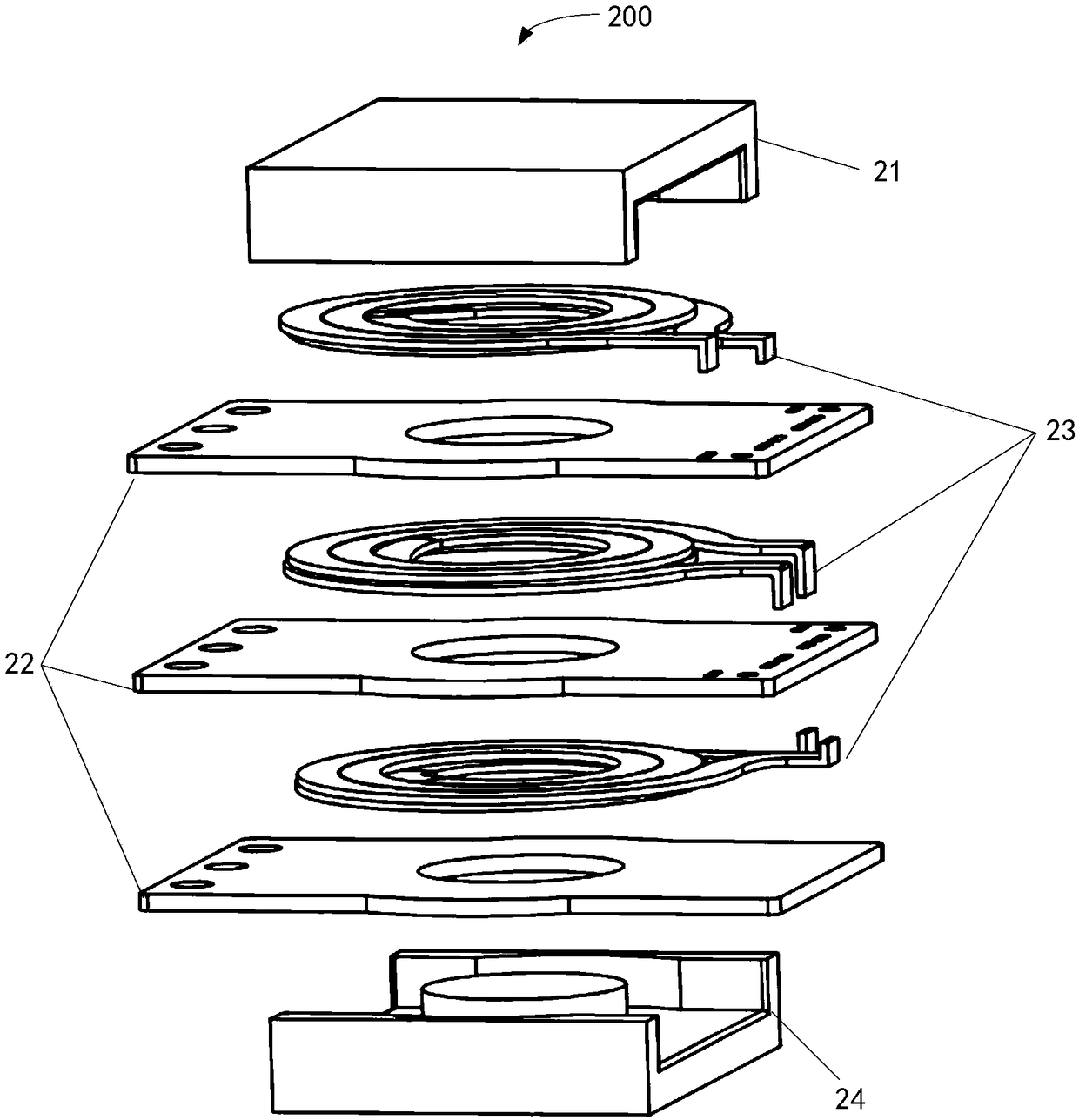
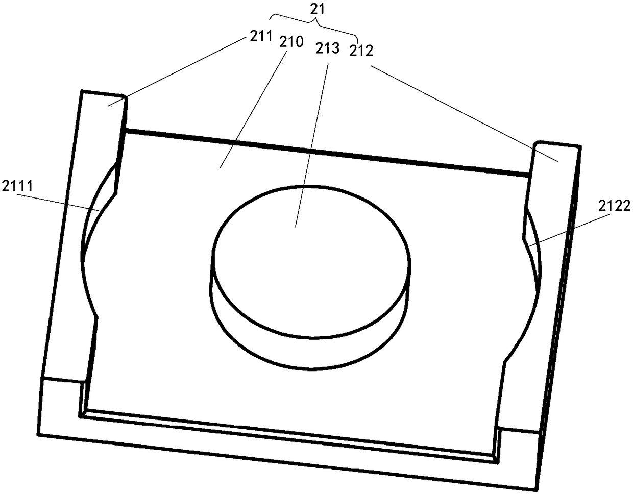
The invention relates to the technical field of planar transformers, in particular to a planar transformer, electronic equipment and a production method of the planar transformer. The planar transformer comprises a first magnetic core, at least one PCB (printed circuit board) winding, at least one pancake coil and a second magnetic core. The first magnetic core, all the PCB windings, all the pancake coils and the second magnetic cores are coaxially assembled into the planar transformer. On the one hand, a primary / secondary coil formed by the PCB windings and the pancake coils has higher overcurrent capability compared with the traditional winding coil; on the other hand, when the primary / secondary coil with more turns is required to be designed, the number of the turns of the pancake coilscan be increased / decreased transversely, the assembling of multiple layers of the primary / secondary coils can be relatively avoided; a proximity effect and stray capacitance are further reduced; thepower density is increased; and a temperature rise is reduced.

Description

technical field [0001] The invention relates to the technical field of planar transformers, in particular to a planar transformer, electronic equipment and a manufacturing method of the planar transformer. Background technique [0002] The transformer uses the principle of electromagnetic induction to realize the conversion of voltage. A transformer includes a primary coil, a secondary coil, and a magnetic core. Generally, users can adjust the number of turns of the primary coil or secondary coil to form a transformer according to product requirements. For example, see figure 1 , figure 1 It is a schematic diagram of the principle of a planar transformer provided by traditional technology. Such as figure 1 As shown, the user constructs a planar transformer by arranging multiple layers of primary coils and secondary coils alternately. [0003] In the process of realizing the present invention, the inventor found that the traditional technology has at least the following ...

Claims


Application Information

Patent Timeline
IPC IPC(8): H01F27/30H01F27/28H01F41/00
CPCH01F27/2804H01F27/2871H01F27/306H01F41/00H01F2027/2819
Inventor 闵运胜赵斌徐旭
Owner UTT ELECTRONICS SZ CO LTD
Learn More