
Negative pressure suction front end and negative pressure suction system

A negative pressure and suction device technology, applied in the field of negative pressure equipment, can solve the problems of poor adsorption effect and low adsorption efficiency, and achieve the effects of complete treatment, elimination of harmful pollution, and guarantee of clarity

Pending Publication Date: 2018-07-31
北京保利健医药技术发展有限责任公司
View PDF5 Cites 0 Cited by
  • Summary
  • Abstract
  • Description
  • Claims
  • Application Information

AI Technical Summary

Problems solved by technology

[0002] At present, electrosurgical equipment ESU, laser knife, high-frequency scalpel and other tools are widely used in open surgery. During the operation, the tissue is destroyed, ablated and decomposed, causing its fine particles to be suspended in the air, resulting in harmful smoke, ultrafine Harmful particles and odors, etc.; in response to this situation, the usual method is to move the hand-held straw to the surgical site for repeated suction during the operation, which only slightly improves the operating environment; however, the above-mentioned treatment methods cannot meet the actual Surgical needs, low adsorption efficiency, poor adsorption effect

Method used


Image

  • Negative pressure suction front end and negative pressure suction system
  • Negative pressure suction front end and negative pressure suction system
  • Negative pressure suction front end and negative pressure suction system

Examples


Embodiment 1

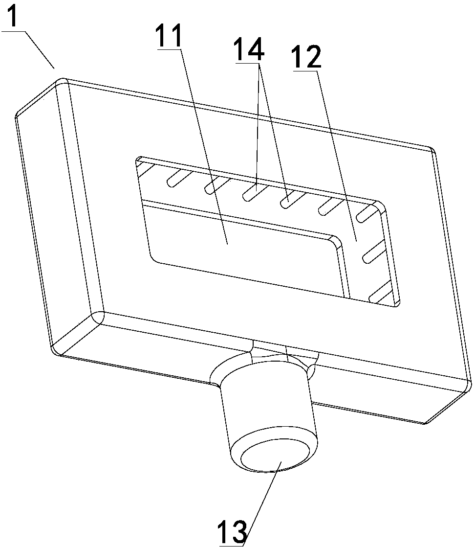
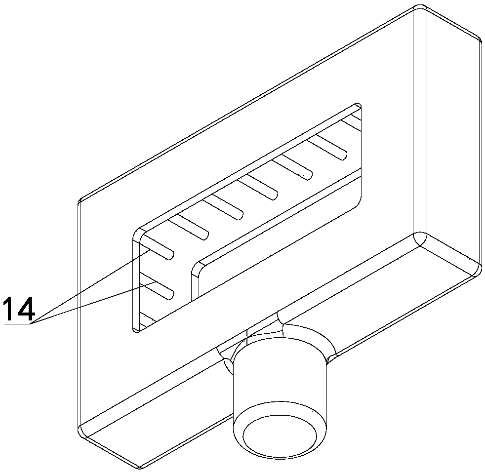
[0040] combine Figure 1-Figure 2 As shown, a negative pressure suction front end provided in Embodiment 1 of the present invention may include a suction cabin 1; the suction cabin 1 may have a ring structure, and the side of the suction cabin 1 facing the area surrounded by the ring structure is provided with a suction port 12, The suction chamber is also provided with a discharge port 13 for communicating with a negative pressure source. Wherein, the area surrounded by the above-mentioned annular structure can form the operating channel 11 for surgery, and the suction port 12 is set towards the operating channel 11, which can absorb smoke, particles and odors at the surgical wound in time.

[0041] In the specific operation, the present invention can provide the necessary passages required for surgical wound operation through the above-mentioned operation channel 11, which can effectively meet the actual needs; the setting of the negative pressure source through the above-me...

Embodiment 2

[0052] The substantial difference between the second embodiment and the first embodiment lies in: the specific setting of the operation channel is different.

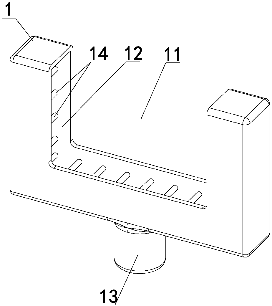
[0053] combine Figure 3-Figure 4 As shown, in the negative pressure suction front end provided in the second embodiment of the present invention, the main structure is similar to that of the first embodiment, the suction cabin 1 also has a ring structure, and the side of the suction cabin 1 facing the area surrounded by the ring structure is provided with a suction port 12. The suction chamber is also provided with a discharge port 13 for communicating with a negative pressure source. For the specific description of the above structure, please refer to the description in Embodiment 1. This embodiment aims to illustrate the difference between the two.

[0054] In this embodiment, the above-mentioned annular structure is a split ring, that is, the above-mentioned operation channel 11 has an opening area partially contai...

Embodiment 3

[0057] The substantial difference between the third embodiment and the first embodiment lies in: the specific setting of the suction cabin is different.

[0058] A negative pressure suction front end provided in Embodiment 3 of the present invention has a main structure similar to that of Embodiment 1. The suction cabin also has a ring structure. The side of the suction cabin facing the area surrounded by the ring structure is provided with a suction port, and the suction cabin is also provided with a suction port. There is a discharge port for connecting with a negative pressure source. For the specific description of the above structure, please refer to the description in Embodiment 1. This embodiment aims to illustrate the difference between the two.

[0059] In this embodiment, the above-mentioned suction chamber may include a porous material and a film wrapped outside the porous material; wherein, the above-mentioned porous material may preferably be a polyurethane sponge....


PUM


Abstract

The invention discloses a negative pressure suction front end and a negative pressure suction system. The negative pressure suction front end comprises a suction tank, wherein the suction tank is of an annular structure; a suction inlet is arranged in the side, facing an area surrounded by the annular structure, of the suction tank; an exhaust port, by which a negative pressure source gets communicated, is additionally arranged in the suction tank; the negative pressure suction system comprises the negative pressure suction front end and a negative pressure suction device, wherein the negativepressure suction device comprises a device housing, a negative pressure generating device which is arranged in the device housing and an adsorption box; and the adsorption box gets communicated withthe exhaust port in the negative pressure suction front end via a connecting tube. The negative pressure suction front end and the negative pressure suction system provided by the invention can be applied to the technical field of negative pressure equipment; with the application of the invention, shortcomings in the prior art can be overcome; harmful smoke as well as superfine harmful particles and smell, which are generated in an operating process, can be instantaneously sucked away; therefore, relatively high adsorption efficiency is achieved and a relatively good adsorption effect is realized.

Description

technical field [0001] The present application relates to but not limited to negative pressure equipment, especially a negative pressure suction front end and a negative pressure suction system. Background technique [0002] At present, electrosurgical equipment ESU, laser knife, high-frequency scalpel and other tools are widely used in open surgery. During the operation, the tissue is destroyed, ablated and decomposed, causing its fine particles to be suspended in the air, resulting in harmful smoke, ultrafine Harmful particles and odors, etc.; in response to this situation, the usual method is to move the hand-held straw to the surgical site for repeated suction during the operation, which only slightly improves the operating environment; however, the above-mentioned treatment methods cannot meet the actual Surgical needs, the adsorption efficiency is low, and the adsorption effect is poor. Contents of the invention [0003] The technical problem solved by this applicat...

Claims


Application Information

Patent Timeline
Patent Type & Authority Applications(China)
IPC IPC(8): A61B90/00
CPCA61B2218/008
Inventor 张胜利
Owner 北京保利健医药技术发展有限责任公司
Learn More