
Glass cooling device

A cooling device and glass technology, applied in glass forming, glass manufacturing equipment, manufacturing tools, etc., can solve the problems of reduced material utilization rate, quality defects of special glass products, difficult to form mold temperature uniform cooling, etc., to improve cooling Efficiency, better quality results

Inactive Publication Date: 2018-07-31
CHONGQING SHUNHUA SAFETY GLASS CO LTD
View PDF6 Cites 0 Cited by
  • Summary
  • Abstract
  • Description
  • Claims
  • Application Information

AI Technical Summary

Problems solved by technology

[0003] The traditional cooling method is to pour the glass liquid on the bottom mold and directly cool it with wind, which is difficult to meet the requirement of uniform cooling of the entire molding mold temperature, and the temperature difference between the middle and the edge is often above 50 degrees Celsius
Especially for the production of large pieces of special glass products with regular shapes (such as glass windows of automobiles), the shape and size are determined, and the heat in the center is concentrated, so the balanced cooling and cooling of the glass liquid is realized, that is, the balanced cooling of the middle and sides of the glass liquid is maintained. It is very difficult to cool down, which leads to quality defects of special glass products, greatly reduces the utilization rate of materials, and hinders the long-term development of the special glass industry

Method used


Image

  • Glass cooling device

Examples


Embodiment

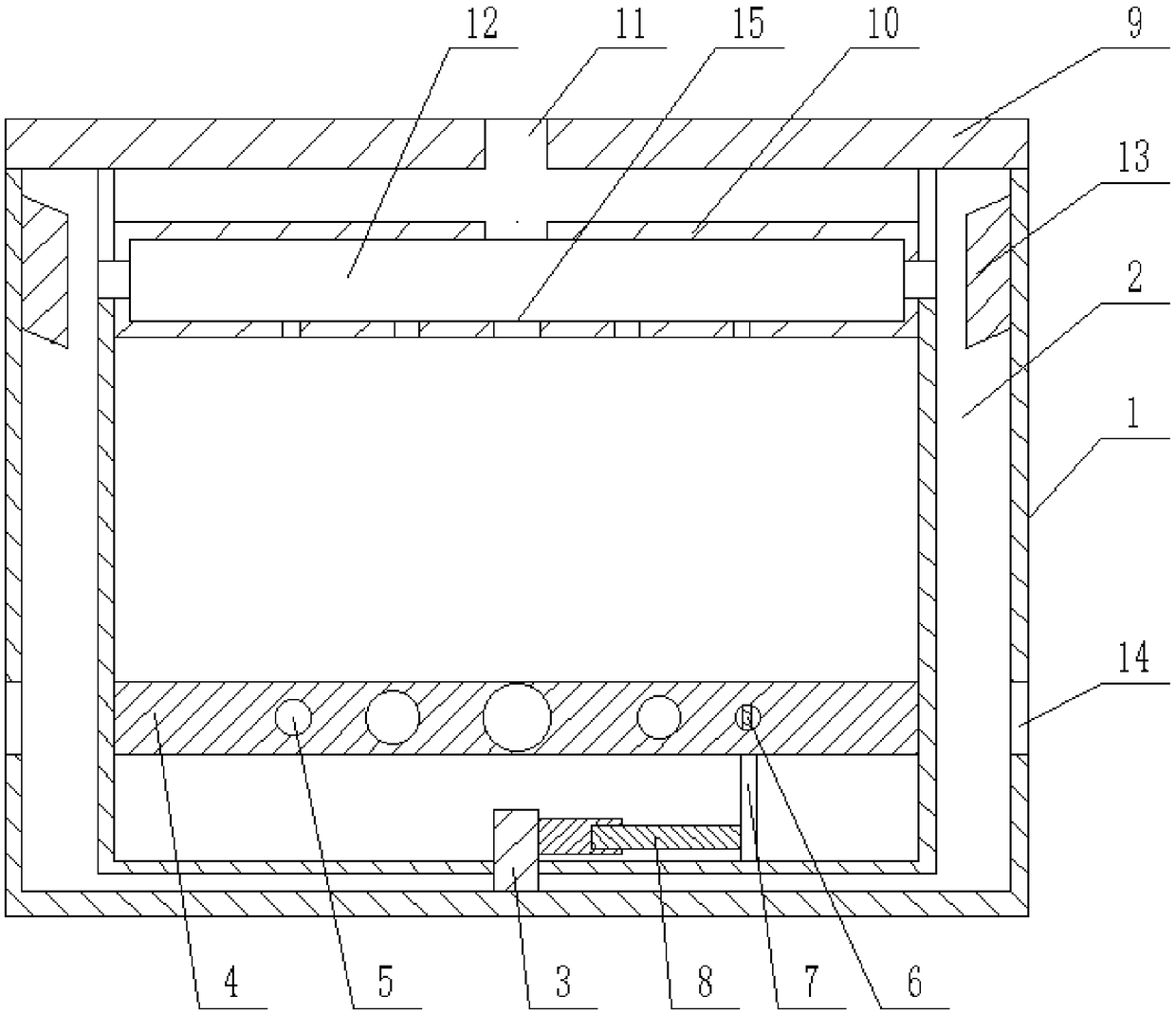
[0022] Glass cooling unit, if attached figure 1 As shown, it includes a mold 1, a ventilation mechanism and a cooling mechanism installed in the mold 1. The side wall of the mold 1 is provided with a conduction chamber 2, and the center of the bottom of the mold 1 is welded with a straight shaft 3.

[0023] The cooling mechanism includes a lower mold 4 for carrying glass. A spiral water pipe 5 whose diameter gradually decreases from the center is installed inside the lower mold 4. A water tank and a water pump are connected to the central nozzle of the spiral water pipe 5. The outer pipe of the spiral water pipe 5 The mouth is also connected with a sink and a water pump. The center position of the spiral water pipe 5 is directly opposite to the center position of the lower die 4. An iron block 6 is installed in the spiral water pipe 5. The bottom end of the lower die 4 is connected with a magnet 7 magnetically matched with the iron block 6, and the bottom end of the lower die...


PUM


Abstract

The invention relates to the technical field of glass processing, in particular to a glass cooling device. The device comprises a mold, a ventilation mechanism and a cooling mechanism. The mold is provided with a connection cavity, and a straight shaft is installed at the center of the mold. The cooling mechanism comprises a lower die, a spiral water pipe, a ventilation device cover plate and an upper die, wherein the spiral water pipe is installed in the lower die, and the diameter of the spiral water pipe is gradually reduced from the center; the spiral water pipe is provided with a water tank and a water pump which are matched with two pipe openings of the spiral water pipe, and the central position of the spiral water pipe is aligned with the central position of the lower die; an ironblock is arranged in the spiral water pipe, the bottom of the lower die is connected with a magnet which is in magnetic fit with the lower die, and the magnet is connected with the straight shaft through a telescopic rod; a vent hole is formed in the cover plate, the upper die is provided with a cooling chamber, and the cooling chamber is communicated with the vent hole; the two ends of the cooling cavity are communicated with the connection cavity, negative pressure blades are arranged in the connection cavity, and an air outlet is formed in the bottom of the connection cavity. When the technical scheme is adopted, the middle part and the edge of glass can be uniformly cooled. Therefore, the device can be widely used for glass cooling.

Description

technical field [0001] The invention relates to the technical field of glass processing, in particular to a glass cooling device. Background technique [0002] The special glass industry is an important industry in our country and plays a very important role in the country's economic construction. In the casting and molding production process of special glass, after the special glass powder is made into clinker from sugar, it enters the kiln for secondary melting, and then needs to be cooled and formed. The temperature of the molten glass coming out of the kiln is between 1200-1500 degrees Celsius, and the temperature needs to be lowered to 600-700 degrees Celsius. [0003] The traditional cooling method is to pour the glass liquid on the bottom mold and directly cool it with wind, which is difficult to meet the requirement of uniform cooling of the entire molding mold temperature, and the temperature difference between the middle and the edge is often above 50 degrees Cels...

Claims


Application Information

Patent Timeline
IPC IPC(8): C03B19/02
CPCC03B19/02
Inventor 袁顺华
Owner CHONGQING SHUNHUA SAFETY GLASS CO LTD
Learn More