
Mini throttling refrigeration system based on novel gas compression device

A gas compression and refrigeration system technology, applied in refrigerators, compressors, refrigeration and liquefaction, etc., can solve the problems of not being able to adapt well to micro-throttle refrigeration systems, unsuitable for the use of micro-gas compressors, and poor response of micro-pumps , to achieve the effect of improving the conversion efficiency and working bandwidth, improving reliability and integration, and no electromagnetic interference

Pending Publication Date: 2018-07-31
ZHEJIANG NORMAL UNIVERSITY
View PDF0 Cites 2 Cited by
  • Summary
  • Abstract
  • Description
  • Claims
  • Application Information

AI Technical Summary

Problems solved by technology

However, because the one-way valve of the valved micropump is a passive valve that can only act after the change of gas pressure, the opening and closing of the valve lag behind the deformation of the driving parts that cause the pressure change in the pump chamber, resulting in the micropump under certain conditions. The response of the valveless micropump is poor, which affects its working performance; and the valveless micropump is prone to more backflow phenomenon due to the lack of one-way valve control during operation, so the output pressure of the valveless micropump will not be too high, which is not suitable for microgas compressors. use
Therefore, the existing miniature gas compressors cannot be well adapted to the miniature throttling refrigeration system

Method used


Image

  • Mini throttling refrigeration system based on novel gas compression device
  • Mini throttling refrigeration system based on novel gas compression device
  • Mini throttling refrigeration system based on novel gas compression device

Examples


Embodiment Construction

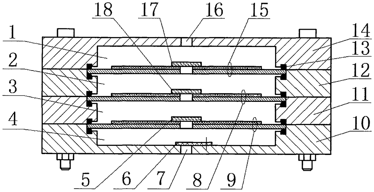
[0016] A micro-throttling refrigeration system based on a novel gas compression device of the present invention is composed of two parts, respectively a novel gas compression device II and a cooling part III.

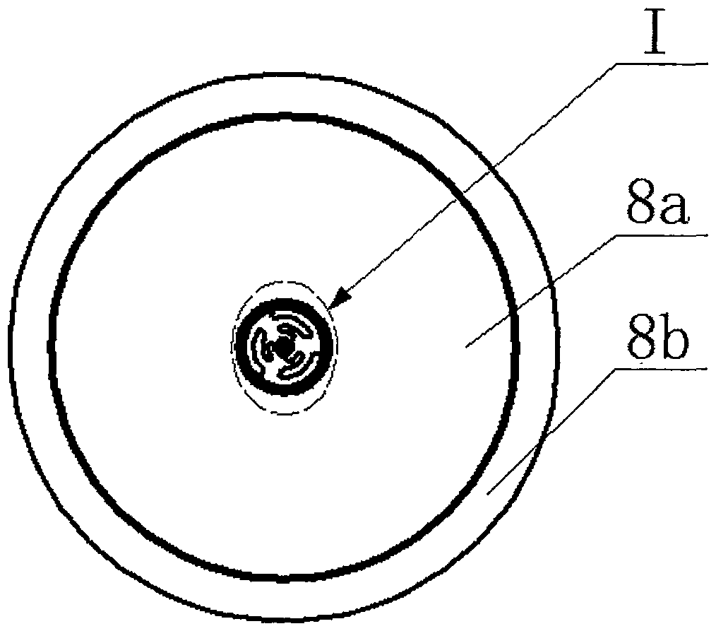
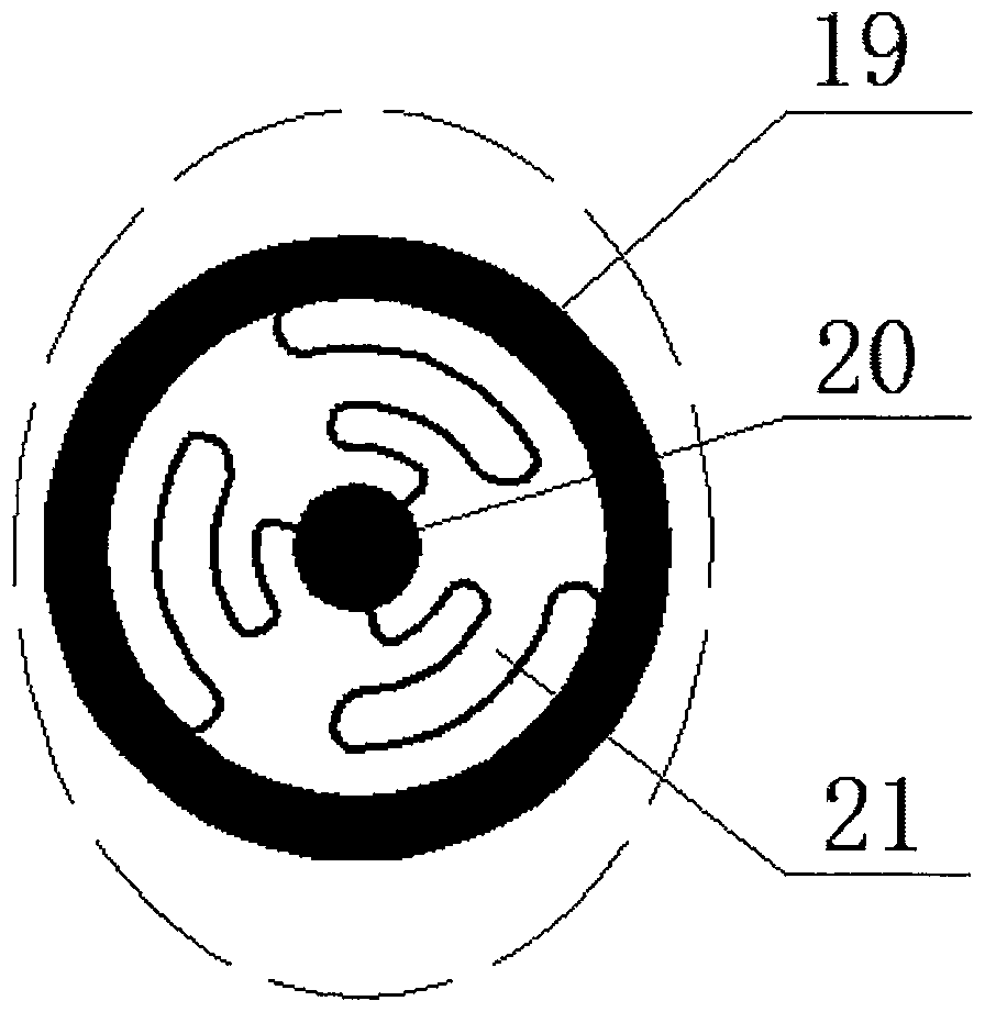
[0017] Such as figure 1 , figure 2 As shown, the novel gas compression device II of the present invention consists of an upper cover 14, an upper pump body 12, a lower pump body 11, a lower cover 10, a sealing ring 13, wheel valves 17, 18, 5, an inlet valve 6 and a piezoelectric vibrator 15 . The piezoelectric vibrators 15, 8, and 9 have central holes in their centers, and wheel valves 17, 18, and 5 are respectively bonded; the upper cover 14, the wheel valve 17, the sealing ring 13 and the piezoelectric vibrator 15 together constitute the upper cover Pump chamber 1; upper pump body 12, piezoelectric vibrator 15, wheel valves 17, 18, sealing ring 13 and piezoelectric vibrator 8 together constitute upper pump chamber 2; lower pump body 12, piezoelectric vibrator 8, wh...


PUM


Abstract

The invention belongs to the field of mini pumps and refrigeration system equipment, and particularly relates to a mini throttling refrigeration system based on a novel gas compression device. The novel gas compression device is composed of an upper cover, an upper pump body, a lower pump cover, a lower cover, sealing rings, wheel type valves, an inlet valve and piezoelectric vibrators; the piezoelectric vibrators and the sealing rings are in press joint through bolts; a center hole is formed in the center of each piezoelectric vibrator, and the wheel type valves are bonded to the centers of the piezoelectric vibrators; an upper cover pump cavity, an upper pump cavity, a lower pump cavity and a lower cover pump cavity are composed of the upper cover, the lower cover, the upper pump body, the lower pump body, the wheel type valves, the sealing rings, the upper piezoelectric vibrator, the middle piezoelectric vibrator, the lower piezoelectric vibrator and the wheel type valves of the piezoelectric vibrators, and pump cavity multi-level compression is achieved; an outlet runner is formed above the upper cover pump cavity; and an inlet runner communicates with the lower cover pump cavity through the inlet valve, and the inlet runner and the outlet runner are connected with a cooling part to form the mini throttling refrigeration system. The mini throttling refrigeration system hasthe features and advantages that the provided mini throttling refrigeration system is high in integration, low in power consumption, free of electromagnetic interference / impacts / noise and prone to microminiaturization.

Description

technical field [0001] The invention belongs to the field of micro-pumps and refrigeration system equipment, in particular to a micro-throttle refrigeration system based on a novel gas compression device. Background technique [0002] In recent years, with the advancement of manufacturing and processing technology, especially the rapid development of microelectromechanical systems (MEMS), micropumps have been widely used in life sciences due to their advantages such as precise control, portability, low power consumption, and small size integration. , biology and microfluidics. With the gradual maturity of liquid micro pump technology, the development of micro gas pumps and micro gas compression devices has become a new focus. [0003] In the research of electronic technology, infrared detection technology, high-temperature superconducting technology and low-temperature material science, many components need to work normally in a certain low temperature environment, so as to...

Claims


Application Information

Patent Timeline
IPC IPC(8): F25B9/00F04B45/047
CPCF04B45/047F25B9/00
Inventor 陈松钱超平罗罕频马继杰郑佳佳
Owner ZHEJIANG NORMAL UNIVERSITY
Learn More