
Method for detecting grouting fullness of prestressed duct of bridge

A channel grouting and detection method technology, which is applied in the direction of elastic testing, machine/structural component testing, measuring devices, etc., can solve problems such as unfavorable stethoscope receiving signals, prestressed channel grouting is not dense, shock echo weakening, etc. , to achieve broad implementation prospects, improve accuracy and work efficiency

Inactive Publication Date: 2018-07-31
菏泽城建工程发展集团有限公司
View PDF3 Cites 3 Cited by
  • Summary
  • Abstract
  • Description
  • Claims
  • Application Information

AI Technical Summary

Problems solved by technology

[0003] In the existing large and medium-sized concrete continuous box girder structures in my country, due to the site construction conditions and technological requirements, the prestressed channels of the bottom plate of the box girder are not completely arranged in a straight line, and some of the bottom slabs are very thick. The laitance and the bottom slab concrete are delaminated. , Hollow, high unevenness, which is not conducive to the stethoscope to receive signals, and some parts of the surface laitance are not in complete contact with the concrete of the bottom plate, forming a weak layer, which has a weakening effect on the shock echo, so it is not suitable to use the shock echo test system
[0004] For this reason, there is an urgent need for a detection method with a wide application range, high accuracy, and effective detection of the fullness of bridge prestressed channel grouting, so as to strictly control the quality of prestressed channel grouting in prestressed concrete bridges, and completely eliminate bridge prestressing. The major safety hazard of tunnel grouting is not dense and full

Method used


Image

  • Method for detecting grouting fullness of prestressed duct of bridge

Examples


Embodiment 1

[0018] The bridge structure in a certain area is a prestressed concrete cable-stayed bridge with double single towers, equal span and single cable plane. The bridge span structure is north-south symmetric, and the two links are independent. system, the aperture combination of the single bridge span structure is 72m+80m+168m+168m+80m+72m. The detection range is: 50 m in the mid-span area of ​​68 m, and 30 m in the mid-span area of ​​72 m (80 m).

[0019] In this embodiment, a middle room with a range of 30 meters in the span of 72 meters is selected for detection. Among them, there are 13 longitudinal prestressed pipes on the floor of the middle chamber, and the detection length is 195m.


PUM


Abstract

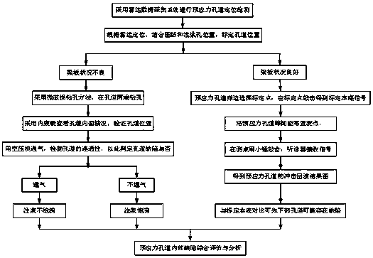
The invention relates to a method for detecting grouting fullness of a prestressed duct of a bridge, and the method comprises the following steps: S1 adopting a radar data acquisition system to perform positioning detection on a bottom plate longitudinal prestressed duct; S2 based on radar positioning combining a drawing and the position of a remaining in-box grouting hole, preliminarily marking the position of the bottom plate longitudinal prestressed duct; S3 adopting a micro-damage drilling method to drill holes at both ends of the bottom plate longitudinal prestressed duct to verify the position of the bottom plate longitudinal prestressed duct; S4 using an air compressor to blow air to detect the connectivity of the bottom plate longitudinal prestressed duct to judge whether the bottom plate longitudinal prestressed duct is defected; and S5 using a single-point impact echo test system to detect the impact echo reflection time of the bottom plate longitudinal prestressed duct, andcomparing the the impact echo reflection time of the bottom plate longitudinal prestressed duct with a calibration reflection time to judge the internal grouting condition of the prestressed duct. Themethod has the advantages of being simple, intuitive, convenient, accurate and practical, can effectively improve the accuracy and working efficiency of detection work, and can be widely used for detecting the grouting fullness of the prestressed duct of the bridge.

Description

technical field [0001] The invention belongs to the technical field of bridge detection, and in particular relates to a method for detecting the fullness of grouting in bridge prestressed tunnels. Background technique [0002] The most commonly used prestressing technology in bridges is post-tensioning prestressing. Post-tensioning prestressing channel grouting is mainly to prevent the corrosion of prestressed tendons, and transfer the prestress to the concrete structure through the condensed slurry to make up for the reserved prestress. Sectional loss due to channels. If the compactness and fullness of the prestressed channel grouting cannot meet the requirements, it will cause corrosion and fracture of the prestressed steel strand, which will directly affect the safety and durability of the bridge. For this reason, the detection methods for the fullness of grouting in bridge prestressed tunnels have become an important research field. At present, the common detection meth...

Claims


Application Information

Patent Timeline
Patent Type & Authority Applications(China)
IPC IPC(8): G01N29/02G01M5/00
CPCG01M5/0008G01M5/005G01N29/02G01N2291/02416
Inventor 周元成田衍雷刘永宋成立李松涛孙孝雷李兰军陈保柱黄鑫孙志翔李北燕王同勋郭慧
Owner 菏泽城建工程发展集团有限公司
Learn More