
Novel laser cutting robot device

A laser cutting and robot technology, applied in laser welding equipment, welding equipment, metal processing equipment, etc., can solve the problems of hidden safety hazards, exposed power supply sheets, difficult disassembly and assembly, etc., and achieves the effect of convenient operation and simple structure

Inactive Publication Date: 2018-08-03
王可迪
View PDF0 Cites 0 Cited by
  • Summary
  • Abstract
  • Description
  • Claims
  • Application Information

AI Technical Summary

Problems solved by technology

[0002] Laser cutting is the use of a focused high-power-density laser beam to irradiate the workpiece, so that the irradiated material is rapidly melted, vaporized, ablated or reached the ignition point, and at the same time the molten material is blown away by the high-speed airflow coaxial with the beam, so as to realize the cutting of the workpiece. Open, the electrical connection interface in the existing laser cutting processing robot generally needs to be locked and connected by screws, the connection method is cumbersome and difficult to disassemble, which affects the work efficiency of installation and disassembly. In addition, the traditional electrical connection interface The power supply sheet is exposed, and there is a big safety hazard

Method used


Image

  • Novel laser cutting robot device
  • Novel laser cutting robot device
  • Novel laser cutting robot device

Examples


Embodiment Construction

[0016] Combine below Figure 1-5 The present invention will be described in detail.

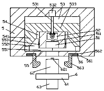
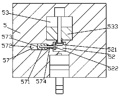
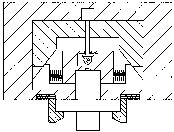
[0017] refer to Figure 1-5 , according to an embodiment of the present invention, a new type of laser cutting robot device, including a plurality of sets of power transmission elements 5 fixedly installed in the front end surface of the power transmission main frame 4 and plugs for mating connection with the power transmission elements 5 Connecting element 6, the base 3 is fixedly installed on the bottom end surface of the main transmission main frame 4, and the bottom end surface of the base 3 is fitted with a rolling wheel 31, and the bottom end surface of the transmission element 5 is provided with an insertion connection groove 51. A first slot 52 is provided inside the conduction element 5 on the upper side of the plug-in slot 51 , and a first slide that expands left and right is provided inside the conduction element 5 on the upper side of the first hole 52 . Groove 53, the inner wal...


PUM


Abstract

The invention discloses a novel laser cutting robot device. The novel laser cutting robot device comprises a plurality of electricity conduction components and inserting connection components; the electricity conduction components are fixedly arranged in the end faces of the front sides of electricity conduction main frames; the inserting connection components are connected with the electricity conduction components in a fit manner; bases are fixedly arranged at the bottom end faces of the electricity conduction main frames; rollers are arranged in the bottom end faces of the bases in a rolling fit manner; inserting connection grooves are formed in the bottom end faces of the electricity conduction components; first hole grooves are formed in the parts, on the upper sides of the insertingconnection grooves, of the electricity conduction components; first sliding grooves are formed in the parts, on the upper sides of the first hole grooves, of the electricity conduction components in aleft and right extending manner; second sliding grooves are symmetrically formed in the inner walls of the left side and the right side of each inserting connection groove; the second sliding groovesextend towards one sides far away from the inserting connection grooves; and third sliding grooves extending up and down are symmetrically formed in the parts, on the left side and the right side ofthe corresponding first hole groove, of each electricity conduction component.

Description

technical field [0001] The invention relates to the field of cutting equipment, in particular to a novel laser cutting robot device. Background technique [0002] Laser cutting is the use of a focused high-power-density laser beam to irradiate the workpiece, so that the irradiated material is rapidly melted, vaporized, ablated or reached the ignition point, and at the same time the molten material is blown away by the high-speed airflow coaxial with the beam, so as to realize the cutting of the workpiece. Open, the electrical connection interface in the existing laser cutting processing robot generally needs to be locked and connected by screws, the connection method is cumbersome and difficult to disassemble, which affects the work efficiency of installation and disassembly. In addition, the traditional electrical connection interface The power supply sheet exposed, there is a big security risk. Contents of the invention [0003] The object of the present invention is to...

Claims


Application Information

Patent Timeline
Patent Type & Authority Applications(China)
IPC IPC(8): B23K26/38B23K26/70
CPCB23K26/38B23K26/70B23K26/702
Inventor 王可迪
Owner 王可迪
Learn More