Device and method for monitoring tool state in cutting process and chip formation

A cutting tool technology, which is applied in the field of monitoring tool status in cutting processing and chip formation, can solve the problems of affecting the acquisition accuracy of AE sensors, distortion of monitoring system monitoring functions, narrow application range, etc., and achieves strong correlation and independence Good performance and guaranteed collection accuracy

Active Publication Date: 2018-08-03
CENT SOUTH UNIV +1
View PDF12 Cites 12 Cited by
  • Summary
  • Abstract
  • Description
  • Claims
  • Application Information

AI Technical Summary

Problems solved by technology

[0006] 1. Since the vibration frequency of the tool and the workpiece during chip formation is high, basically exceeding 10KHZ, an AE sensor is required, and the AE sensors of the existing monitoring system are directly installed on the workpiece or tool. During the process, the noise signal caused by the vibration of the tool or workpiece will be mixed with the signal that the AE sensor needs to collect, thus affecting the collection accuracy of the AE sensor and distorting the monitoring function of the monitoring system
[0007] 2. It is impossible to correlate the signal collected by the AE sensor with the shape of the chip, the state of the tool and the workpiece, whether there is contact friction between the chip and the rake face of the tool, and the state of tool wear. Effective monitoring and analysis has a narrow scope of application

Method used


Image

  • Device and method for monitoring tool state in cutting process and chip formation
  • Device and method for monitoring tool state in cutting process and chip formation
  • Device and method for monitoring tool state in cutting process and chip formation

Examples


Embodiment Construction

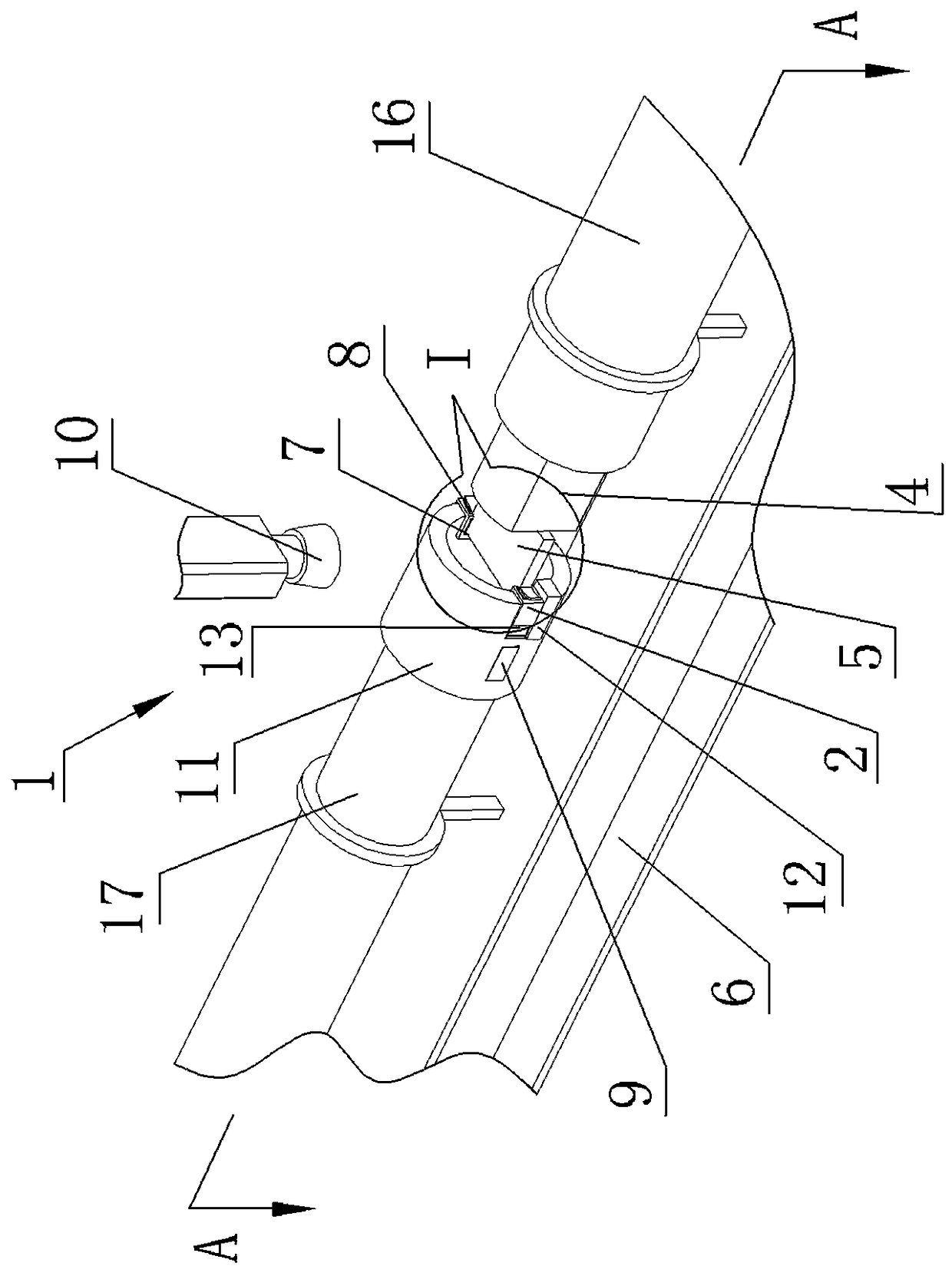
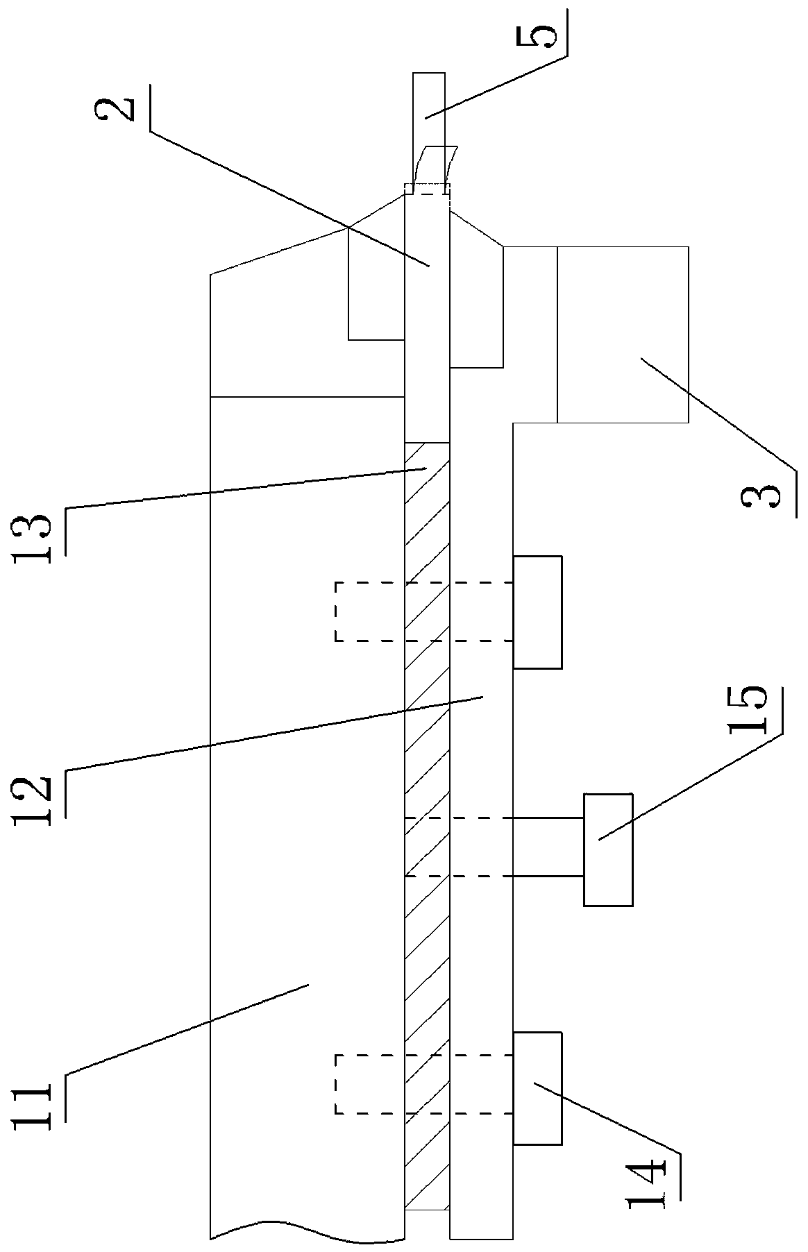
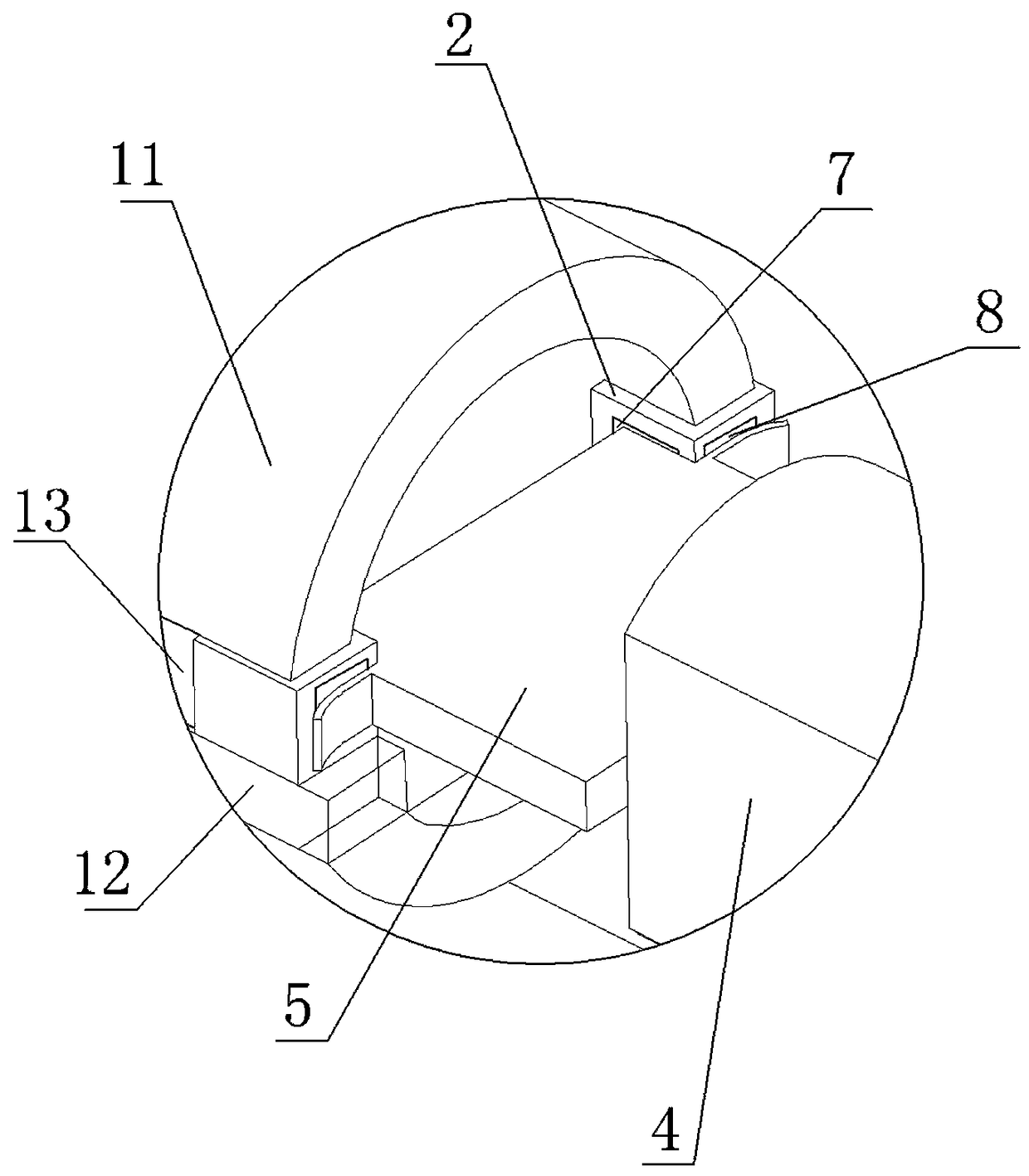
[0035] From Figure 1 to Figure 3 It can be seen that the device for monitoring the cutting tool state in the cutting process and chip formation of the present invention includes a tool holder 1, a tool 2, an AE signal collector 3, a fixture 4, a workpiece 5, a test platform 6, a piezoelectric force Sensor one 7, piezoelectric force sensor two 8, surface strain gauge 9, high-speed CCD camera 10 and a data acquisition system for signal acquisition and storage, wherein

[0036] The tool holder 1 includes a main holder 11, a secondary holder 12, a heat insulation and vibration damping pad 13, several connecting bolts 14 and a number of adjustment bolts 15, and the cutter 2 and the heat insulation and vibration damping pad 13 are arranged side by side on the main holder 11. Between the auxiliary holder 12, the thread on the connecting bolt 14 rotates in the forward direction, and the thread on the adjusting bolt 15 rotates in the reverse direction. The holder 11 is threaded, the ...


PUM


Abstract

The invention discloses a device and a method for monitoring the tool state in a cutting process and chip formation. The device comprises a tool and an AE signal collector which are mounted on a toolholder, a workpiece, a test platform and a data acquisition system, wherein the tool holder includes a main clamp holder, a sub-clamp-holder and a heat-insulating damping pad, the tool and the heat-insulating damping pad are arranged side by side between the main clamp holder and the sub-clamp-holder, the sub-clamp-holder is locked on the main clamp holder in the forward direction through connecting bolts penetrating through the heat-insulating damping pad, the sub-clamp-holder reversely and tightly abuts against the main clamp holder through an adjusting bolt, and the AE signal collector is mounted on the sub-clamp-holder; and a first piezoelectric force transducer is arranged on the flank surface of the tool, a second piezoelectric force transducer is arranged on the rake face of the tool, a surface strain meter is mounted on the main clamp holder, and a high speed CCD camera is mounted above the tool. According to the device and the method for monitoring the tool state in the cutting process and the chip formation, AE signal has high acquisition precision, good independence and high relevance.

Description

technical field [0001] The invention relates to the technical field of machining, in particular to a device and method for monitoring the state of a tool in cutting and chip formation. Background technique [0002] High-speed cutting is an advanced manufacturing process much higher than conventional cutting speed. It can not only greatly improve the processing efficiency of parts, reduce the processing cost, but also make the surface processing quality and processing accuracy of parts reach a higher level. High-speed processing has been widely used in aviation, aerospace, automobile and ultra-precision micromachining and other fields. [0003] In the process of high-speed cutting, a series of situations such as tool wear, chipping, breakage, failure, chip formation, fracture, and cutting interruption often occur. These conditions have a specific impact on the machining process and the state of the tool. During the machining process, these accidents will affect the cutting ...

Claims


Application Information

Patent Timeline
Patent Type & Authority Applications(China)
IPC IPC(8): B23Q17/09B23Q17/24
CPCB23Q17/0952B23Q17/2452Y02P70/10
Inventor 陈雪林唐进元周元生刘安民
Owner CENT SOUTH UNIV
Why Eureka
Try Eureka