Blocking structure for inner container enameling process and enameling process

A liner and process technology, which is applied in the field of enamel processing, can solve the problems of dry film damage in the nozzle area, stuck screw teeth, damage of the nozzle ceramic layer, etc., and achieves the effect of improving the quality of enamel coating.

Active Publication Date: 2018-08-03
GREE ELECTRIC APPLIANCES INC
View PDF7 Cites 4 Cited by
  • Summary
  • Abstract
  • Description
  • Claims
  • Application Information

AI Technical Summary

Problems solved by technology

[0004]The enamelling process is manually dipped in the glaze slurry with a cotton swab to refill the dropped dry film coating in the nozzle area, and the dropped enamel in the nozzle area The powder is extremely difficult to clean. Using a high-pressure air gun may cause the remaining dry film in the nozzle area to be destroyed. It can only be cleaned manually with a wet cloth, which is time-consuming and laborious and cannot be guaranteed to be cleaned.
[0005]In the existing flow enamelling process, some special tooling is used to seal the nozzle, which can prevent the enamel slurry from leaking from the inner wall steps, but there are The following problems: The enamel slurry is well attached to the contact surface of the metal substrate (such as the middle section of the inner tank, the pipe joint). After the process of flowing and drying, the enamel slurry changes from a wet film to a dry film state. , it will make the enamel dry film break into powder, that is, the porcelain layer of the nozzle is destroyed, and at the same time, it is taken out by the tooling and dropped into the pipe joint. If there are threads, the threads will be stuck.

Method used


Image

  • Blocking structure for inner container enameling process and enameling process
  • Blocking structure for inner container enameling process and enameling process
  • Blocking structure for inner container enameling process and enameling process

Examples


Embodiment Construction

[0034] The present invention is described below based on examples, but the present invention is not limited to these examples. Those of ordinary skill in the art will appreciate that the drawings provided herein are for illustration purposes and are not necessarily drawn to scale.

[0035] Unless the context clearly requires, throughout the specification and claims, "comprises", "comprises" and similar words should be interpreted in an inclusive sense rather than an exclusive or exhaustive meaning; that is, "including but not limited to" meaning.

[0036] In the description of the present invention, it should be understood that the terms "first", "second" and so on are used for descriptive purposes only, and cannot be interpreted as indicating or implying relative importance. In addition, in the description of the present invention, unless otherwise specified, "plurality" means two or more.

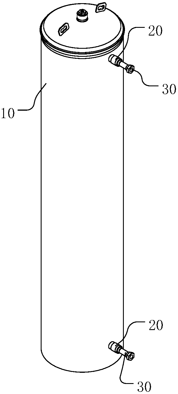
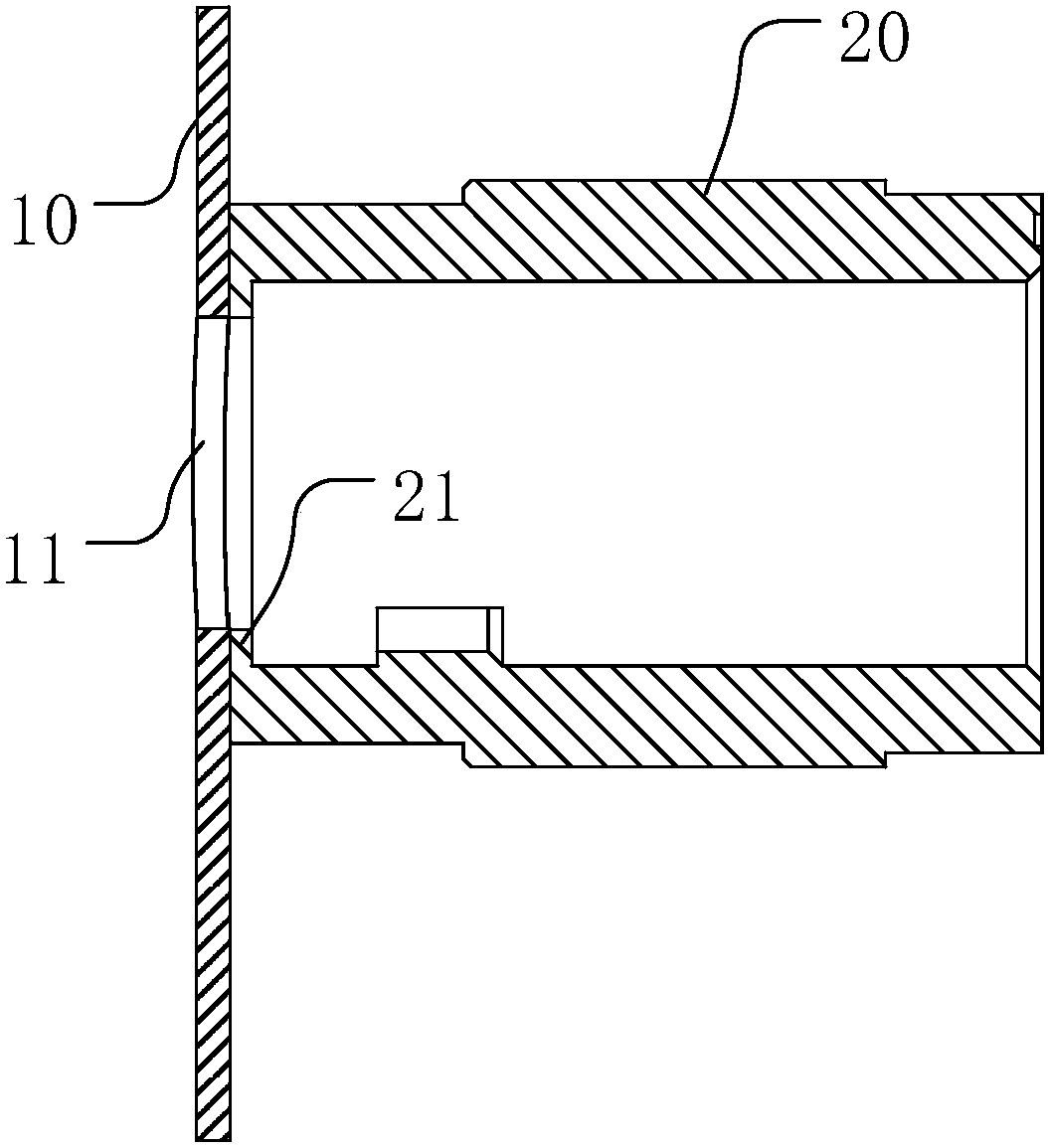
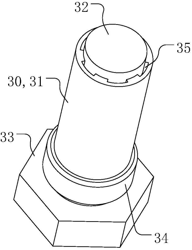
[0037] The liner flow-boiling process sealing structure provided by the present inv...


PUM

PropertyMeasurementUnit
lengthaaaaaaaaaa
thicknessaaaaaaaaaa

Abstract

The invention discloses a blocking structure for an inner container enameling process and the enameling process. The blocking structure for the inner container enameling process comprises a blocking part and a protruding part. The protruding part is arranged on the blocking part, and when the blocking structure is inserted into a pipe joint, part of the structure of the protruding part is locatedin a through hole, communicating with the pipe joint, in an inner container. Clearances exist between the protruding part and the hole wall of the through hole and between the protruding part and theinner wall of the pipe joint. According to the blocking structure, the blocking part cooperates with the protruding part, the pipe joint can be blocked in the process of carrying out the enameling process on the inner wall of the inner container, glaze slip is prevented from flowing into the pipe joint in the enameling or enamel spraying process, and therefore the glaze slip in the pipe joint doesnot need to be cleared after the enameling process is completed. Besides, the protruding part is located in the through hole, communicating with the pipe joint, in the inner container, the clearanceis formed between the protruding part and the through hole, it can be avoided that missing areas exit in the enameling process, and enameling quality is improved.

Description

technical field [0001] The invention relates to the technical field of enamel processing, in particular to a plugging structure for the flow-enameling process of an inner tank and a flow-enameling process. Background technique [0002] Heat pump hot water machine enamel water tank liner cylinder is composed of the middle section of the liner, the upper and lower heads, and several pipe joints welded on the middle section and the head. The pipe joint is a key part of the external water circuit and a key quality area that affects the anti-corrosion performance of the entire water tank liner. [0003] The enamel liner is generally prepared by the flow enamelling process, which needs to go through the processes of welding→flow enameling→spray enamelling→dryingsintering. However, when the inner pot is flow enameled, the structure changes drastically because the joints are fixed on the middle section of the liner by welding. Therefore, the quality control of the joint area is di...

Claims


Application Information

Patent Timeline
Patent Type & Authority Applications(China)
IPC IPC(8): C23D5/00
CPCC23D5/005
Inventor 范召卿陈昌中于娜王成根陶云吴扬军谭德强张斌施景娥黄开东
Owner GREE ELECTRIC APPLIANCES INC
Why Eureka
Try Eureka