Universal-type wide energy rotary jetting engine

A general-purpose engine technology, applied to engine components, machines/engines, mechanical equipment, etc., can solve the problems of low engine thermal efficiency, narrow use of energy, high vibration and noise, etc., and achieve low noise, easy maintenance, and operation no vibration effect

CN108361109AActive Publication Date: 2018-08-03余四艳
8 Cites 6 Cited by

Patent Information

Authority / Receiving Office
CN · China
Patent Type
Applications(China)
Current Assignee / Owner
Publication Date
2018-08-03

Smart Images

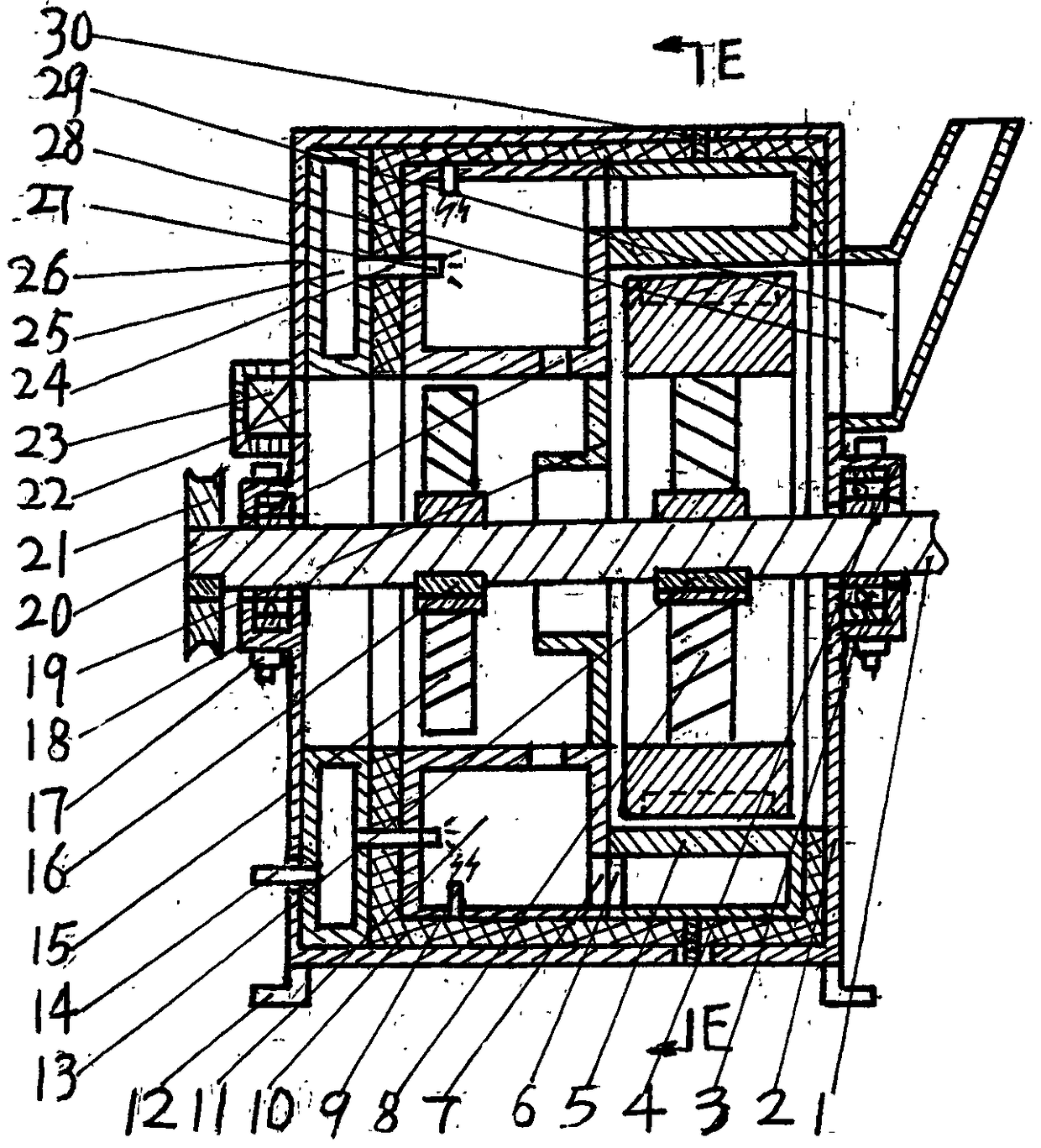
  • Figure 1
    Figure 1
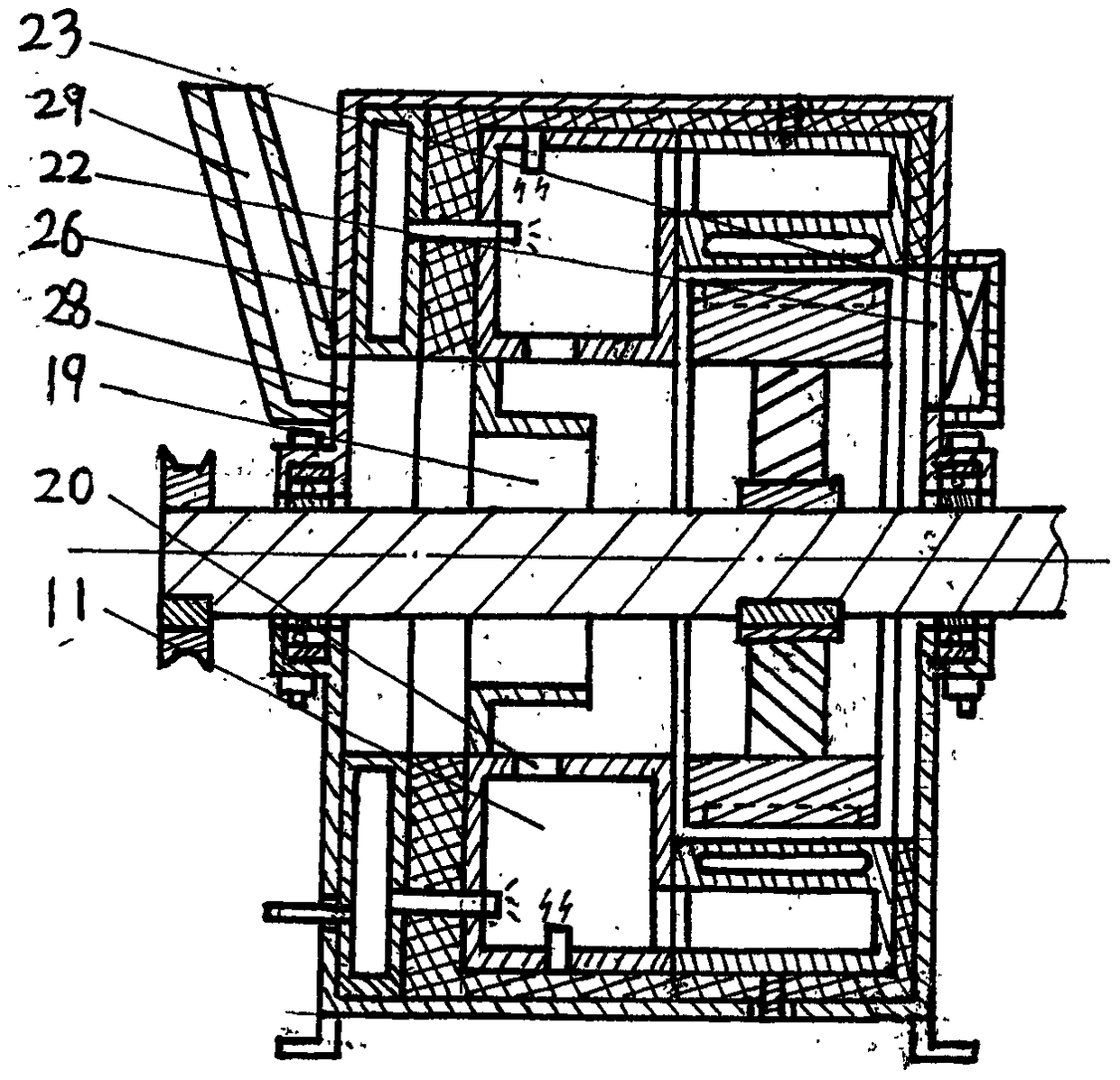
  • Figure 2
    Figure 2
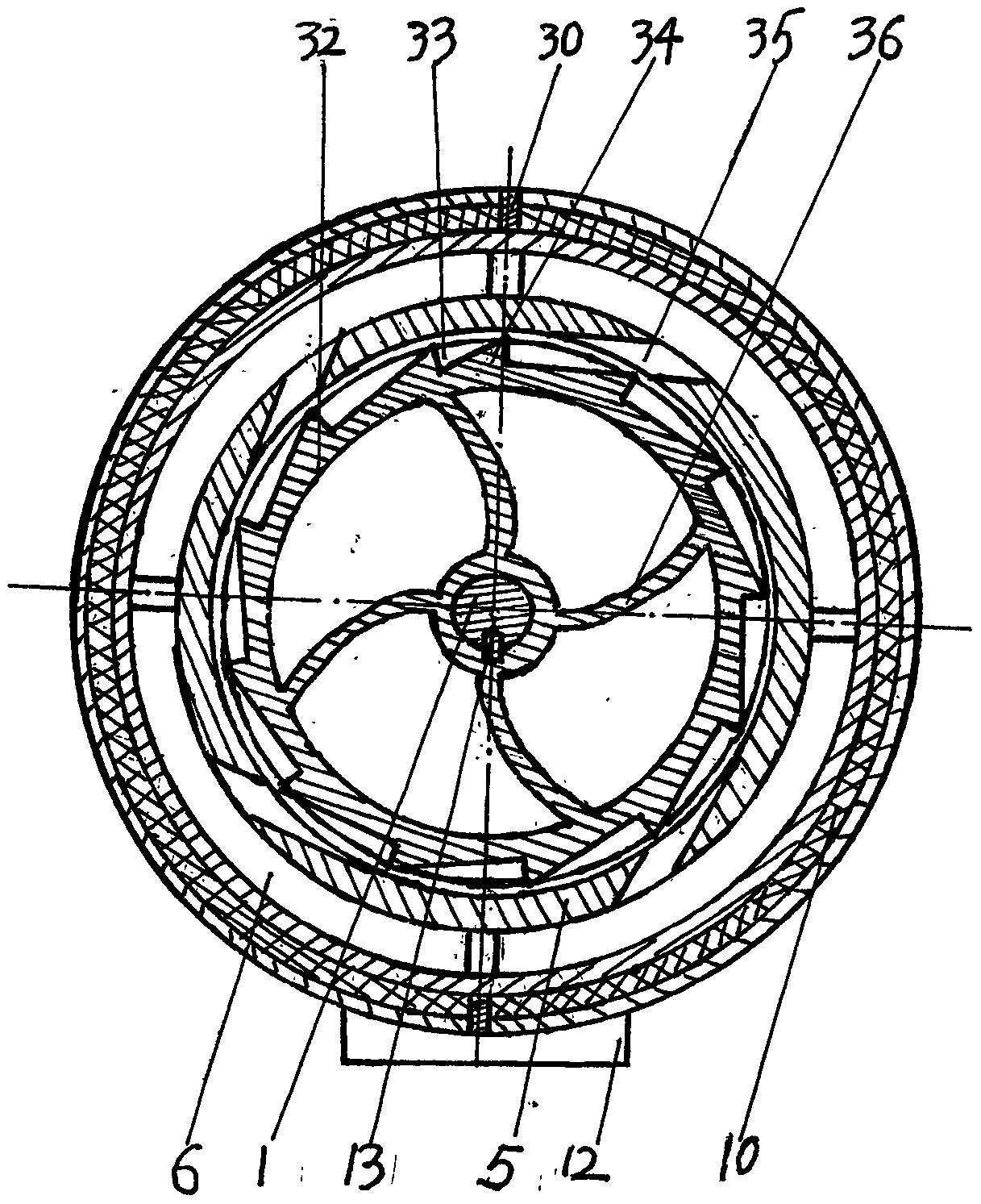
  • Figure 3
    Figure 3
Patent Text Reader

Abstract

The invention discloses a universal-type wide energy rotary jetting engine. The universal-type wide energy rotary jetting engine is a power device adopting a brand new rotary jetting driving technology which is completely different from the current common piston and turbine driving principle. The universal-type wide-energy rotary jetting engine is mainly composed of a main shaft, an annular combustor, a charging turbine, a spraying ring, a power wheel and the like. Fuel and air which is pressed into the annular combustor through the charging turbine mixedly burns to generate high-pressure fuelgas, the high-pressure gas enters the spraying ring and then is sprayed out from the spraying ring at a high speed so as to drive the power wheel to rotate, and the rotating power wheel drives the main shaft to rotate so as to drive the charging turbine to rotate for air inlet and power generation. The universal-type wide-energy rotary jetting engine adopts the brand new, ingenious and scientificdriving principle and exquisite and reasonable design, and thus the universal-type wide-energy rotary jetting engine has the ultra-high heat transfer efficiency, meanwhile has the characteristics ofbeing simple in structure, ultra-low in manufacturing cost, small in size, easy to maintain and repair, free of vibration, small in noise, stable in operation, wide in application energy and the like,can be universally applicable to all aspects such as aviation, vehicles and ships, and really is the revolutionary engine.
Need to check novelty before this filing date? Find Prior Art

Description

technical field

[0001] The invention relates to a power device which converts the heat energy generated by the mixed combustion of chemical fuel and air inside the body into mechanical energy and outputs power to the outside. Background technique

[0002] At present, the power plants appearing in the world can be mainly divided into four types according to the characteristics of the power source: piston engine, rotary engine, gas turbine engine, and gas ramjet engine. The operating principle of piston engine and rotary engine is basically the same, and the thermal energy generated by the combustion of fuel and air is converted into mechanical energy through the cooperation of cylinder and piston or similar mechanism; gas turbine engine uses high-speed gas flow The impeller on the impact shaft rotates, and the impeller drives the shaft to rotate, thereby converting heat energy into mechanical energy; the working principle of the gas ramjet engine is completely different from ...

Examples

Embodiment 1

[0035] Such as figure 1 As shown, the general-purpose wide-energy jet engine includes a main shaft 1, a bearing 3, a fuel injection device 23, an ignition device 9, an air filter device 23, an intake turbocharger 15, etc., and other auxiliary components, with an exhaust outlet 28 , the air intake window 22 and the upper housing 26 of the upper bearing sleeve 4, etc., and the lower housing 2 with the support fixing seat 12, the lower bearing sleeve 18, etc. are connected and closed by the connecting bolts 17 to form a complete housing together, and the inside of the housing is closed. Enclosed to form a relatively closed hollow cylindrical inner space; the upper and lower shell bearing sleeves 4 and 18 are butted and closed together to form a complete bearing sleeve, and the two bearings 3 installed on the main shaft 1 are respectively fixed and installed in these two complete bearing sleeves. In the bearing sleeve; in the complete internal space of the shell, around the main s...

Embodiment 2

[0037] Such as figure 2As shown, another specific embodiment of the present invention can be completed by making the following changes to the specific embodiment of Embodiment 1: remove the intake turbocharger 15 and its fixed key 16; change the installation position of the intake adjustment plate, and the The annular disk of the air regulating plate 19 is fixedly connected with the outer surface of the inner ring cylindrical surface under the end face of the annular combustion chamber 11 where the fuel pressure stabilizing ring 25 abuts, and the cylinder on the air intake regulating plate 19 extends into the annular combustion chamber 11 In the ring cylinder; the air inlet 20 on the side wall of the ring cylinder of the annular combustion chamber 11 is close to the annular disc part of the air intake adjustment plate 19; the tail gas outlet 28 and the air inlet window 22 in the embodiment 1 The positions are exchanged, and the layout and arrangement of other components are t...