Piston-cylinder unit used for forming machine and forming machine

A cylinder unit, molding machine technology, applied in mechanical equipment, fluid pressure converter, fluid pressure actuating device, etc., to achieve the effect of simple structure design

Pending Publication Date: 2018-08-03
ENGEL AUSTRIA
View PDF12 Cites 1 Cited by
  • Summary
  • Abstract
  • Description
  • Claims
  • Application Information

AI Technical Summary

Problems solved by technology

However, said accumulators always require the use of relatively complex hy

Method used


Image

  • Piston-cylinder unit used for forming machine and forming machine
  • Piston-cylinder unit used for forming machine and forming machine
  • Piston-cylinder unit used for forming machine and forming machine

Examples


Embodiment Construction

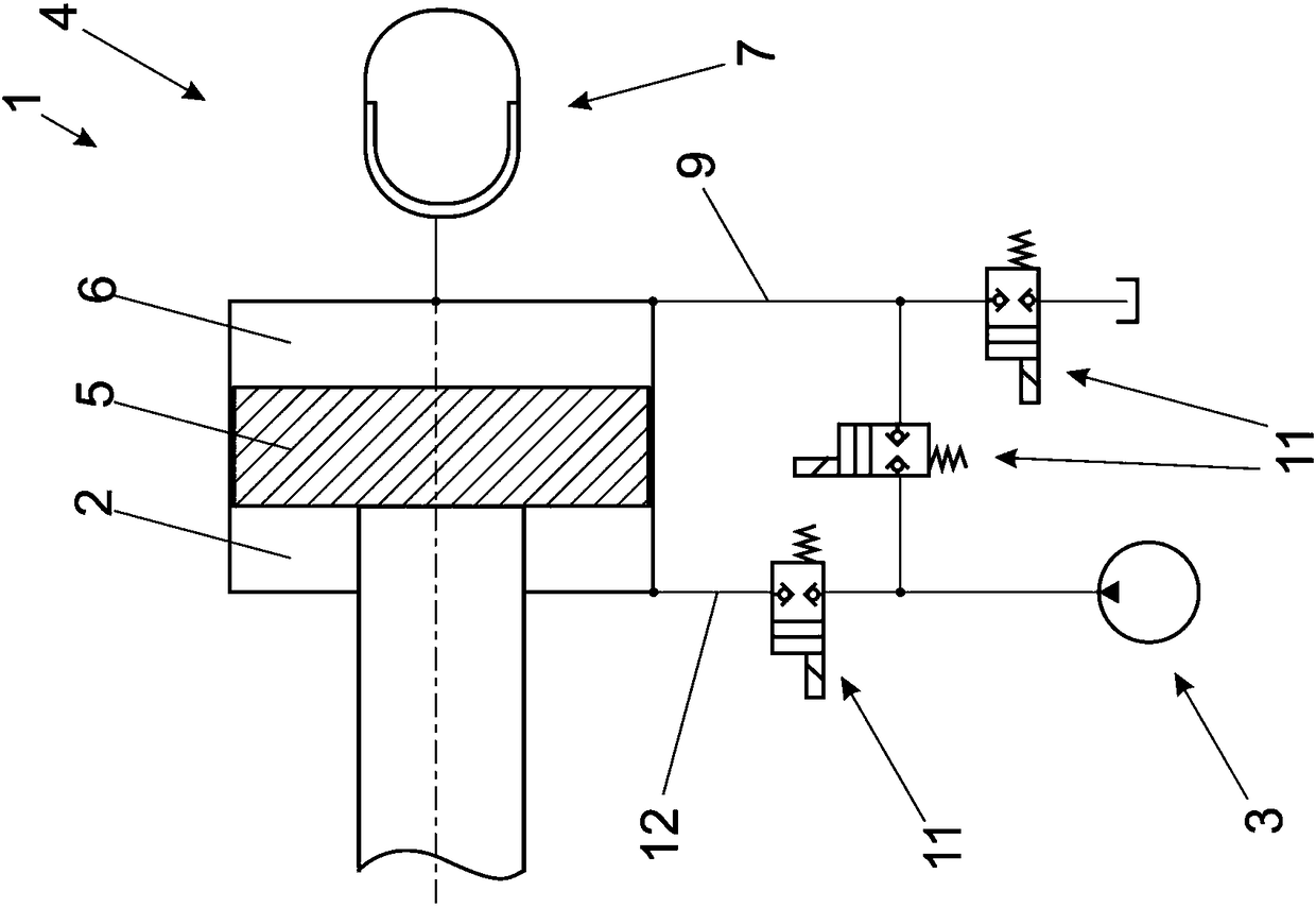
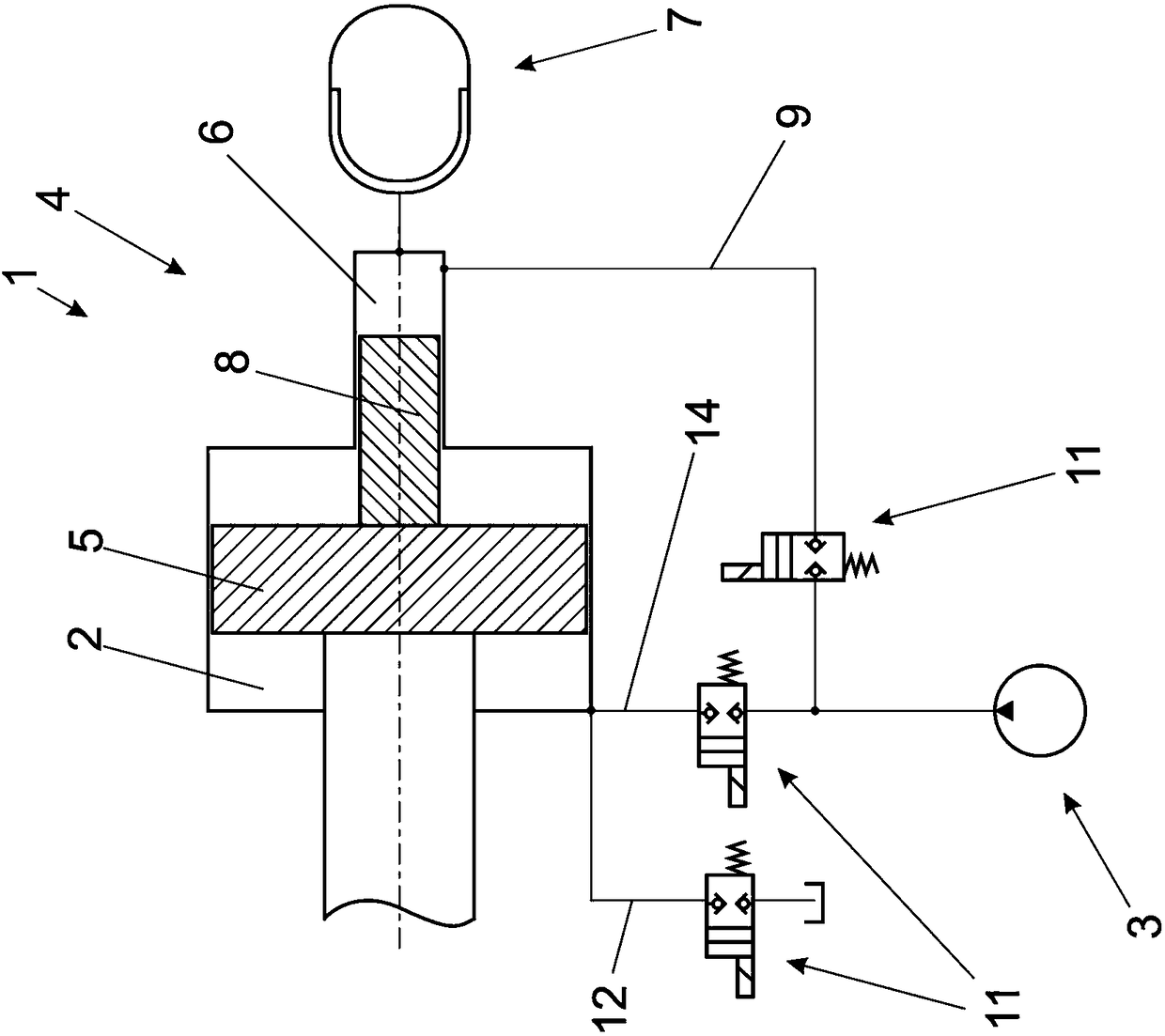
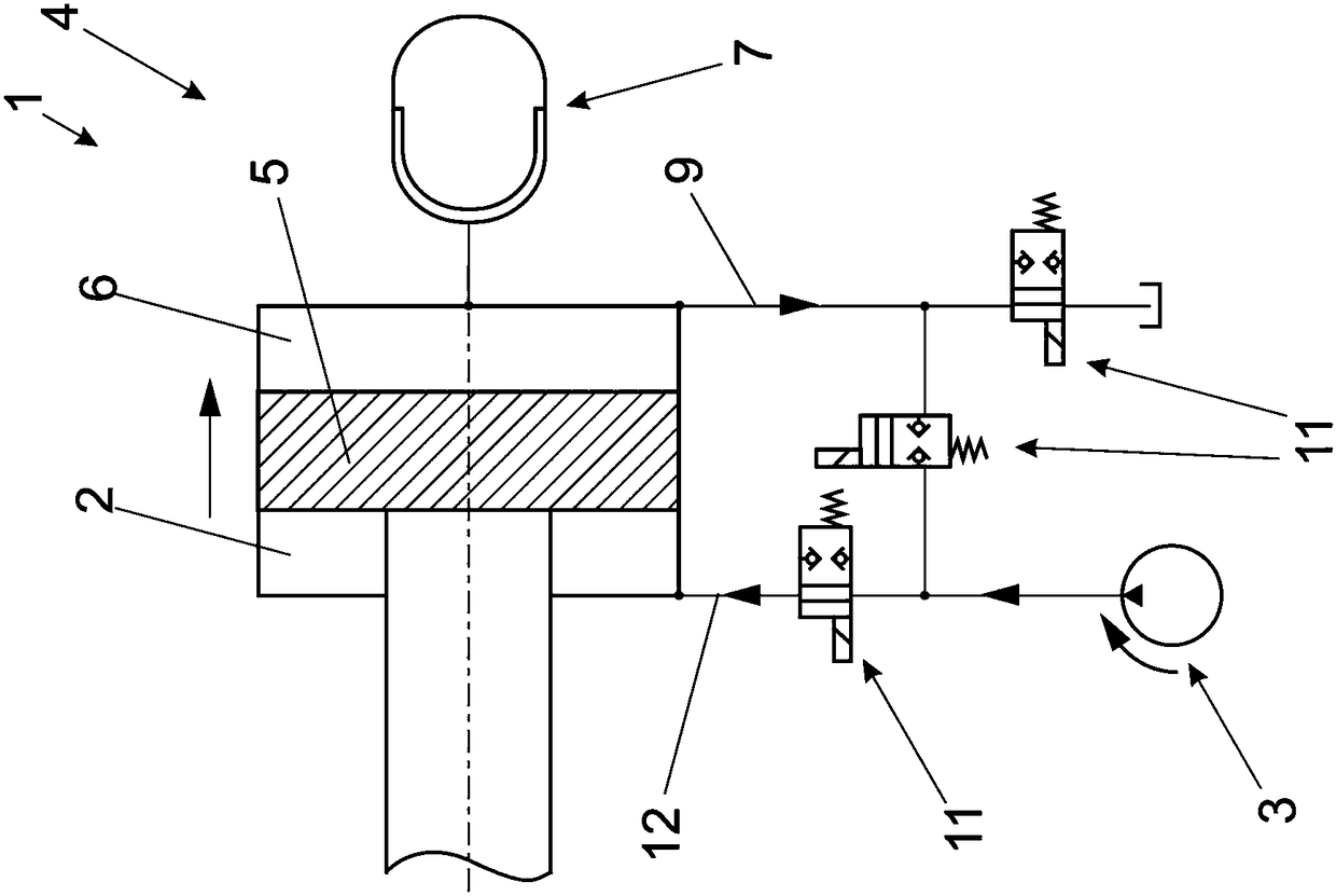
[0040] Figure 1a A piston-cylinder unit 1 according to the invention is shown with a first chamber 2 , a piston 5 and a second chamber 6 . The first chamber 2 on the shank side is used, for example, to act with clamping force in a clamping unit 15 of an injection molding machine. The first chamber 2 is connected to the pump 3 for this purpose. The second chamber 6 is then connected to the pressure accumulator 7 .

[0041] in press Figure 1a In the preferred embodiment, the discharge line 12 is at the same time the input line 14 to the first chamber 2 . A non-return valve 11 is also arranged in the discharge line 12 , and the second chamber 6 is also connected to the pump 3 in addition to the pressure accumulator 7 , ie via the connecting line 9 . A connection from the second chamber 6 to a tank (not referenced) for hydraulic fluid is also established via this connecting line 9 . Two check valves 11 are also located in the connecting line 9, one of which is used for the co...


PUM


Abstract

The invention relates to a piston-cylinder unit used for a forming machine. The unit comprises a first cavity (2) and a hydraulic pump (3). The hydraulic pump is used for being connected with the first cavity (2) for loading hydraulic fluids under pressure. The unit also comprises a reset device (4) used for resetting a piston (5) of a piston-cylinder unit (1) along the direction basically opposite to the acting direction of the first cavity (2). The reset device (4) is equipped with a second cavity (6) of the piston-cylinder unit (1) and a pressure accumulator (7). The pressure accumulator (7) is connected with the second cavity (6) and/ or the pressure accumulator and the second cavity are integrally constructed. The reset device (4) is configured for resetting the piston (5) to a basicposition for reset. The pressure accumulator is completely depressurized at the basic position.

Description

technical field [0001] The invention relates to a piston-cylinder unit for a molding machine according to the features of the preamble of claim 1 . Background technique [0002] Molding machines are understood here to mean injection molding machines, die-casting machines, press-forming machines and similar machines. [0003] Such a piston-cylinder unit comprises a first chamber, a hydraulic pump connected to the first chamber in order to act upon the first chamber with hydraulic fluid under pressure, and for orienting the piston of the piston-cylinder unit in a direction of action with said first chamber A reset device that resets in substantially the opposite direction. A reset device for the piston-cylinder unit can be used in the molding machine when only the action of the piston-cylinder unit in the direction of action of the first chamber is important for the molding cycle itself. The piston-cylinder unit must then be brought back into the starting position, for which...

Claims


Application Information

Patent Timeline
IPC IPC(8): F15B15/14F15B3/00F15B1/08
CPCB29C45/4005B29C45/6728F15B21/14F15B1/08F15B3/00F15B15/1423B29C45/67B29C45/82B29C2045/824F15B2211/7716F15B2211/7053F15B2211/625F15B2211/212F15B2211/205F15B15/1476
Inventor A·洛纳克尔
Owner ENGEL AUSTRIA
Why Eureka
Try Eureka