High-voltage switch cabinet with efficient damping performance

A technology of high-voltage switchgear and shock absorption performance, which is applied in the details of substation/switch layout, seismic equipment, substation/distribution device shell, etc. and other problems, to achieve the effect of saving procurement costs, overcoming work fatigue, and efficient protection

Inactive Publication Date: 2018-08-03
湖州练市天龙纺织有限公司
9 Cites 0 Cited by

AI-Extracted Technical Summary

Problems solved by technology

[0002] High-voltage switchgear refers to the role of on-off, control or protection in power system power generation, transmission, distribution, power conversion and consumption. High-voltage switchgear is used as Shanghai Eaton general equipment network cabinet, etc., and the voltage level is 3.6 kV-550kV electrical products, high-voltage isolating switch and grounding switch, high-voltage load switch, high-voltage automatic reclosing and sectionalizer, high-voltage operating mechanism, high-voltage explosion-proof power distribution device and high-voltage switchgear, etc., mainly applicable to power plants, Substations, petrochemicals, metallurgical steel rolling, light industry and textiles, factories and mines, residential quarters, high-rise buildings and other different occasions, with the development of technology and the upgrading of operating equipment, the requirements for mobile substations are getting higher and higher, and the voltage level is also increasing. From 10kV to 35kV or even 66kV, and with the increase of the voltage level, the volume of the high-voltage part of the mobile substation is getting larger and larger, so the high-voltage switchgear is bulky and heavy in structure, which makes the box difficult to transport. For many electronic components, when the cabinet is placed on the ground, if the ground is shaken by large machines or other factors, the cabinet is easy to slide and shift; during transportation, the cabinet is easy to shake, If it is bumped for a long time, the electronic components inside the cabinet are also easily damaged, thus causing safety accidents. In the prior art, for example, the invention patent with application number 201220683914.9 includes a backing plate for the high-...

Abstract

The invention discloses a high-voltage switch cabinet with efficient damping performance. A machine base is installed on the lower surface of a machine cabinet, the lower surface of the machine base is movably connected with the upper surface of the machine cabinet, a fixing corner brace is installed on the outer wall of the machine base, the inner wall of the fixing corner brace is connected withthe outer wall of the machine base, and a loop bar is installed on the upper surface of the fixing corner brace; the lower surface of the loop bar is connected with the upper surface of the fixing corner brace, a jacking rod is installed on the inner wall of the loop bar, and the outer wall of the jacking rod is movably connected with the inner wall of the loop bar. According to the high-voltageswitch cabinet with the efficient damping performance, through cooperation among a hooking plate, a first torsion spring, a second torsion spring, a clamping plate, a pushing plate and the loop bar, waste of the resources of the high-voltage switch cabinet with the efficient damping performance is avoided under the action of the jacking rod and the hooking plate during installation, more convenience is provided for assembly and disassembly, work fatigue of operation workers is avoided, and the switch cabinet is suitable for popularization and application.

Application Domain

Substation/switching arrangement casingsAnti-seismic devices

Technology Topic

Torsion springHooking +3

Image

  • High-voltage switch cabinet with efficient damping performance
  • High-voltage switch cabinet with efficient damping performance
  • High-voltage switch cabinet with efficient damping performance

Examples

  • Experimental program(1)

Example Embodiment

[0020] The technical solutions in the embodiments of the present invention will be clearly and completely described below in conjunction with the accompanying drawings in the embodiments of the present invention. Obviously, the described embodiments are only a part of the embodiments of the present invention, rather than all the embodiments. Based on the embodiments of the present invention, all other embodiments obtained by those of ordinary skill in the art without creative work shall fall within the protection scope of the present invention.
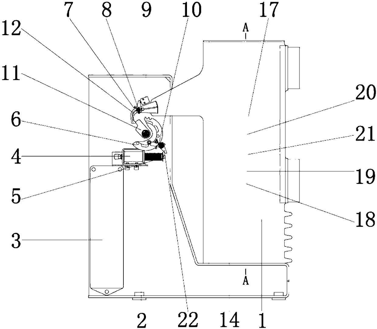
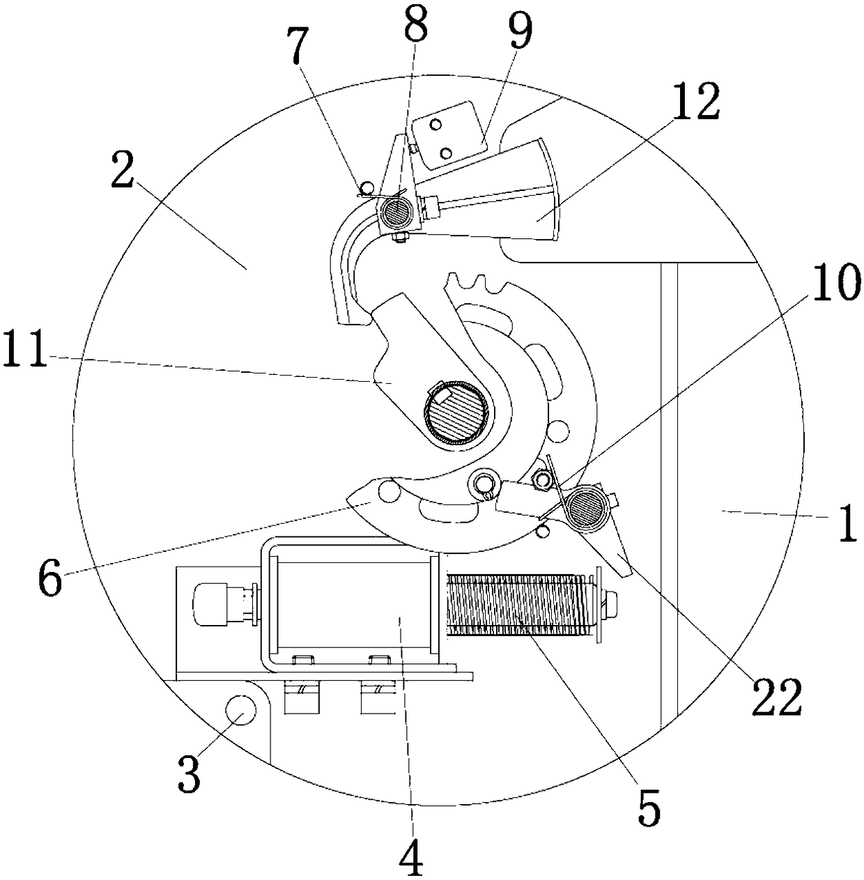
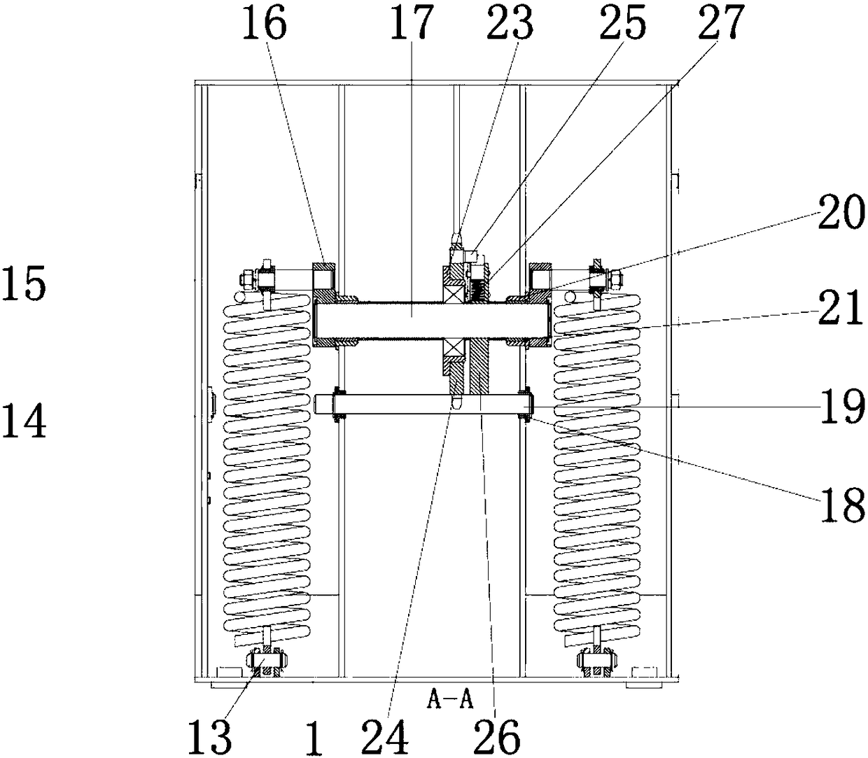
[0021] See Figure 1-4 , The present invention provides a technical solution: a high-voltage switch cabinet with high-efficiency shock absorption performance, including a cabinet 1 for installing and fixing a first compression spring 14, and a base 2 mounted on the lower surface of the cabinet 1 for fixing the cabinet 1. The lower surface of the base 2 is movably connected with the upper surface of the cabinet 1. A fixed angle 3 is installed on the outer wall of the base 2 to install the fixed sleeve rod 4, and the inner wall of the fixed angle 3 is connected to the outer wall of the base 2. , The upper surface of the fixed angle code 3 is installed with a sleeve rod 4 for installing and fixing the top rod 5. The lower surface of the sleeve rod 4 is connected with the upper surface of the fixed angle code 3, and the inner wall of the sleeve rod 4 is installed with a top rod 5, Used to push the push plate 22, the outer wall of the top rod 5 is movably connected with the inner wall of the sleeve rod 4, the outer wall of the base 2 is equipped with a turntable 6 for pushing the chuck 11, and the inner wall of the turntable 6 is movably connected to the outer wall of the base 2 , The inner wall of the turntable 6 is provided with a clamping plate 11 for fixing the push plate 22, the inner wall of the clamping plate 11 is movably connected with the outer wall of the machine base 2, and the outer wall of the turntable 6 is installed with a push plate 22 for cooperating with the ejector rod 5 to drive the turntable 6 Rotate, the inner wall of the push plate 22 is connected with the outer wall of the turntable 6. The outer wall of the push plate 22 is sleeved with a second torsion spring 10, and the elastic coefficient of the second torsion spring 10 is 1-10N/CM, which is used to drive the push plate 22 Reset, the inner wall of the second torsion spring 10 is connected to the outer wall of the push plate 22, the outer wall of the push plate 22 is movably connected to the inner wall of the turntable 6 through the second torsion spring 10, and the inner wall of the turntable 6 is movably connected to the outer wall of the chuck 11, and the cabinet A hook plate 12 is installed on the outer wall of 1 to be slidably engaged with the card plate 11. The inner wall of the hook plate 12 is movably connected to the outer wall of the cabinet 1, and a baffle plate 9 is provided above the hook plate 12 to restrict the hook plate 12 Displacement, the inner wall of the baffle 9 is connected to the outer wall of the base 2. The outer wall of the hook plate 12 is equipped with a pin 8 for fixing the hook plate 12 and installing the first torsion spring 7. The inner wall of the pin 8 is connected to the hook plate 12 The outer wall is movably connected. The outer wall of the pin 8 is sleeved with a first torsion spring 7. The elastic coefficient of the first torsion spring 7 is between 1-10N/CM, which is used to drive the hook plate 12 to reset. The inner wall of the first torsion spring 7 The hook plate 12 is movably connected with the outer wall of the baffle 9 through the first torsion spring 7 and the inner wall of the hook plate 12 is movably connected with the outer wall of the clamping plate 11, and the outer wall of the top rod 5 is movably connected with the push plate 22 The inner walls of the cabinet 1 are movably connected, and fixed pads 13 are installed on the left and right sides of the inner wall of the cabinet 1 to install and fix the first compression spring 14. The lower surface of the fixed pad 13 is connected with the upper surface of the inner wall of the cabinet 1. A first compression spring 14 is installed on the inner wall of 13 and the elastic coefficient of the first compression spring 14 is between 1-10N/CM, which is used to drive the chip 17 to reset inside the cabinet 1. The outer wall of the first compression spring 14 and the fixed pad The inner wall of the block 13 is connected, the upper surface of the first compression spring 14 is installed with a pull rod 15 for connecting and fixing the side plate 16, the lower surface of the pull rod 15 is connected with the upper surface of the first compression spring 14, and the outer wall of the pull rod 15 is installed The side plate 16 is used to fix the chip 17, the inner wall of the side plate 16 is connected with the outer wall of the pull rod 15, and the side plate 16 Chip 17 is installed between the inner walls of the chip 17, which is an electronic component in the high-voltage switch cabinet. The left and right sides of the outer wall of the chip 17 are equipped with rubber sleeves 21 for connecting and fixing the chip 17, when the chip 17 is connected to the side plate 1. The connection is stronger. The outer wall of the rubber sleeve 21 is sleeved with a rubber pad 20 to reinforce the connection between the chip 17 and the rubber sleeve 21. The inner wall of the rubber pad 20 is connected to the outer wall of the rubber sleeve 21, and the inner wall of the rubber sleeve 21 is connected to the chip. 17 is connected to the outer wall, and the outer wall of the chip 17 is sleeved with a splint 23 to fix the chip 17 on the inner wall of the cabinet 1, when the chip 17 is connected to the inner wall of the cabinet 1 more firmly, and the inner wall of the splint 23 is connected to the outer wall of the chip 17 , The inner wall of the splint 23 is installed with a spacer 28 to relieve the external impact force received by the chip 17, the outer wall of the spacer 28 is connected with the inner wall of the splint 23, and the outer wall of the splint 23 is installed with a pole 24 for connecting and fixing the fetters 3 On the inner wall of the cabinet 1, the inner wall of the upright rod 24 is connected to the outer wall of the splint 23, and the right outer wall of the upright rod 24 is equipped with a short rod 25 for connecting the splint 23 and the clamp rod 26, and the left outer wall of the short rod 25 Connected to the right outer wall of the vertical rod 24, the right side of the clamping plate 23 is provided with a clamping rod 26 for fixing the chip 17, the left external wall of the clamping rod 26 is adjacent to the right external wall of the clamping plate 23, and the right side of the vertical rod 24 The outer wall is connected to the left outer wall of the clamping rod 26 through a short rod 25. The inner wall of the clamping rod 26 is equipped with a second compression spring 27. The elastic coefficient of the second compression spring 27 is 1-10N/CM, which is used to relieve the chip 17 from receiving The external impact force prevents the chip 17 from trembling or shaking and affecting the normal use of the chip 17. The outer wall of the second compression spring 27 is movably connected to the inner wall of the clamping rod 26, and the outer wall of the chip 17 is connected to the inner wall of the side plate 16, and the chip 17 A cross bar 19 is provided below to fix the chip 17 and the splint 23. Washers 18 are installed on the left and right sides of the outer wall of the cross bar 19 to increase friction. When the cross bar 19 is connected to the cabinet 1 more firmly, the washer 18 The inner wall of the cross bar 19 is connected with the outer wall of the cross bar 19, which is used to make the connection between the cross bar 19 and the gasket 18 more stable, and the outer wall of the cross bar 19 is connected with the inner wall of the cabinet 1.
[0022] A high-voltage switchgear with high-efficiency damping performance. The high-voltage switchgear with high-efficiency damping performance consists of cabinet 1, frame 2, fixed angle code 3, sleeve rod 4, ejector rod 5, turntable 6, and first torsion spring 7. Pin 8, baffle 9, second torsion spring 10, card plate 11, hook plate 12, fixed pad 13, first compression spring 14, pull rod 15, side plate 16, chip 17, washer 18, cross bar 19. The rubber pad 20, the rubber sleeve 21, the push plate 22 and the splint 23 are composed of parts. The main matching dimensions of the parts, especially the interference fit dimensions and related accuracy, should be reviewed before assembly. The same part uses multiple screws ( When tightening the bolts, the screws (bolts) need to be tightened crosswise, symmetrically, gradually and evenly. Use an angle grinder and a file to fix the cabinet 1, frame 2, fixed angle 3, sleeve rod 4, ejector rod 5, and turntable 6. , The first torsion spring 7, the pin 8, the baffle 9, the second torsion spring 10, the card plate 11, the hook plate 12, the fixed pad 13, the first compression spring 14, the pull rod 15, the side plate 16, the chip 17, The burrs on the surface and connection of the gasket 18, the cross bar 19, the rubber pad 20, the rubber sleeve 21, the push plate 22 and the splint 23, and then apply anti-rust paint on the surface and the connection. The welding is firm, and there should be no false welding. Phenomenon, all parts need to be cleaned with kerosene, rolling bearings are cleaned with gasoline, and no debris is allowed on the surface of the parts. Surface parts such as the frame, the turntable and the compressor support are polished, scraped, and the surface is sprayed with the specified color. Connecting rods, tie rods, stop rods, top covers, etc., all positioning and pressing devices are all oxidized (blackened), and all mating parts, sealing parts, and screw connections are lubricated with grease, the unprocessed surface is painted with gray paint, and the inner surface is painted Red paint, flexible adjustment and rotation, reliable positioning and clamping, fixed on the ground with expansion bolts, tooling manufacturing unit is responsible for installation and adjustment to normal, production and use must ensure that the stack can be interchanged up and down, the diagonal deviation is within ±3mm, After welding, perform anti-rust treatment and then apply blue paint. The "factory name", "tooling number" and "box number" are sprayed with white paint on the position shown in the figure. The font is boldface, except for the front, left, right and back Use 1.5mm thick hot plate to weld the seal, add 3.0mm thick hot plate to the bottom, and the remaining 50X50X4.0 rectangular tube. Before welding, remove rust, oil, moisture and other impurities on the surface of the weldment. The welding rod must be dried to prevent air intrusion. The welding zone causes pores and cracks and reduces the joint performance. Short arc welding should be used as much as possible. The residence time of the heat-affected zone at high temperature should not be too long to avoid coarse grains. When welding fillet welds, the first weld of multi-layer butt welding Deep and narrow grooves should be avoided for seams and single-layer single-sided welds to prevent incomplete penetration and slag inclusion defects. For multilayer welding, the last layer of welds should be welded continuously. The thickness is not more than 5mm. When the rigidity of the weldment increases, the cracking tendency of the weldment will also increase. Therefore, the weldment with high welding rigidity should be preheated before welding and stress relief after welding. The fixed cushion 13 is fixed in the cabinet 1, the first compression spring 14 is fixed on the fixed cushion 13, and the first compression spring is fixed by the tie rod 15. 14 is fixed on the pull rod 15, and the side plate 16 is connected with the pull rod 15, so that the side plate 16 fixes the chip 17 inside the side plate 16, so that the first compression spring 14 can relieve the vibration or vibration of the chip 17 due to shaking , Install the rubber pad 20 and the rubber sleeve 21 at the junction of the side plate 16 and the chip 17 to make the connection between the side plate 16 and the chip 17 firmer. Install the stop 9 and the hook plate 12 on the outer wall of the cabinet 1, and set the pin 8 Installed inside the hook plate 12, the first torsion spring 7 is installed on the outer wall of the pin 8 so that the first torsion spring 7 can drive the hook plate 12 to reset, and the turntable 6 is installed on the outer wall of the base 2, using the push plate 22 and The turntable 6 is connected, and a second torsion spring 10 is installed on the outer wall of the push plate 22, so that the second torsion spring 10 drives the push plate 22 and the turntable 6 to rotate, and a clamping plate 11 is installed on the inner side of the turntable 6 so that the clamping plate 11 can interact with the hook plate. 12 Sliding and snapping, fix the fixed angle code 3 on the outside of the machine base 2, install the sleeve rod 4 and the ejector rod 5 on the top of the fixed angle code 3, so that the ejector rod 5 can slide inside the sleeve rod 4. When in use, Install the cabinet 1 on the base 2. The hook plate 12 on the cabinet 1 is slidably clamped with the clamping plate 11 fixed on the base 2 under the action of the first torsion spring 7. At this time, the cabinet 1 and the base 2 are fixed When separated, push the ejector rod 5 in the sleeve rod 4, the ejector rod 5 pushes the push plate 22, the push plate 22 drives the turntable 6 to rotate under the action of the second torsion spring 10, and the turntable 6 pushes the chuck 11 and the hook plate 12 Take off the cabinet 1 and complete the assembly work of the high-voltage switch cabinet with high-efficiency shock absorption performance.
[0023] In the description of the present invention, it should be understood that the terms "coaxial", "bottom", "one end", "top", "middle", "other end", "upper", "one side", "top" "," "inside", "front", "center", "both ends", etc. indicate the orientation or positional relationship based on the orientation or positional relationship shown in the drawings, and are only for the convenience of describing the present invention and simplifying the description. It does not indicate or imply that the pointed device or element must have a specific orientation, be constructed and operated in a specific orientation, and therefore cannot be understood as a limitation of the present invention.
[0024] In the present invention, unless otherwise clearly specified and limited, the terms "installation", "setting", "connection", "fixing", "spinning" and other terms should be understood in a broad sense. For example, it may be a fixed connection or It can be detachably connected or integrated; it can be mechanically connected or electrically connected; it can be directly connected or indirectly connected through an intermediary, and it can be the internal communication of two components or the interaction between two components Unless specifically defined otherwise, those of ordinary skill in the art can understand the specific meanings of the above terms in the present invention according to specific circumstances.
[0025] Although the embodiments of the present invention have been shown and described, those of ordinary skill in the art can understand that various changes, modifications, and substitutions can be made to these embodiments without departing from the principle and spirit of the present invention. And variations, the scope of the present invention is defined by the appended claims and their equivalents.

PUM

no PUM

Description & Claims & Application Information

We can also present the details of the Description, Claims and Application information to help users get a comprehensive understanding of the technical details of the patent, such as background art, summary of invention, brief description of drawings, description of embodiments, and other original content. On the other hand, users can also determine the specific scope of protection of the technology through the list of claims; as well as understand the changes in the life cycle of the technology with the presentation of the patent timeline. Login to view more.

Similar technology patents

Solar heat storage type vacuum heat pipe

Owner:南京百阳合能源科技有限公司

Ship rotary shaft system instantaneous rotational speed measurement device and method

InactiveCN109870588AEasy to install and maintainLow installation position requirements
Owner:NANJING UNIV OF SCI & TECH

Assembled modular lamphouse

InactiveCN109961709AImprove astigmatism effectEasy to install and maintain
Owner:方迪勇

Sealed bearing

Owner:LEIYANG XINDAWEI TECH

Classification and recommendation of technical efficacy words

  • Easy to install and maintain
  • Reduce the difficulty of operation
Why Eureka
Try Eureka