
Oriented punch riveting system

A punching riveting, guided technology, applied in the field of punching riveting, can solve the problems of different thickness and width of the riveted parts, disc riveting points and actual riveting points, etc., to achieve low production cost, high production efficiency and high automation. Effect

Inactive Publication Date: 2018-08-07
安徽汇精智能工业科技有限公司
View PDF0 Cites 0 Cited by
  • Summary
  • Abstract
  • Description
  • Claims
  • Application Information

AI Technical Summary

Problems solved by technology

[0004] In the prior art, some enterprises have transport mechanisms for better automated production. Workers place the plates on one end of the transport mechanism, and transport the plates to the end of the riveting mold through the transport mechanism. When stamping and riveting, the sheet will move along one end of the riveting die, but in actual situations, the thickness and width of different parts to be riveted are not the same. It is not completely uniform contact. In this case, the sheet will be offset to a certain extent. The offset caused by this process will cause the specified riveting points on the sheet to be inconsistent with the actual riveting points.

Method used


Image

  • Oriented punch riveting system
  • Oriented punch riveting system
  • Oriented punch riveting system

Examples


Embodiment Construction

[0047] In order to make the technical means, creative features, goals and effects achieved by the present invention easy to understand, the present invention will be further elucidated below in conjunction with specific diagrams and examples.

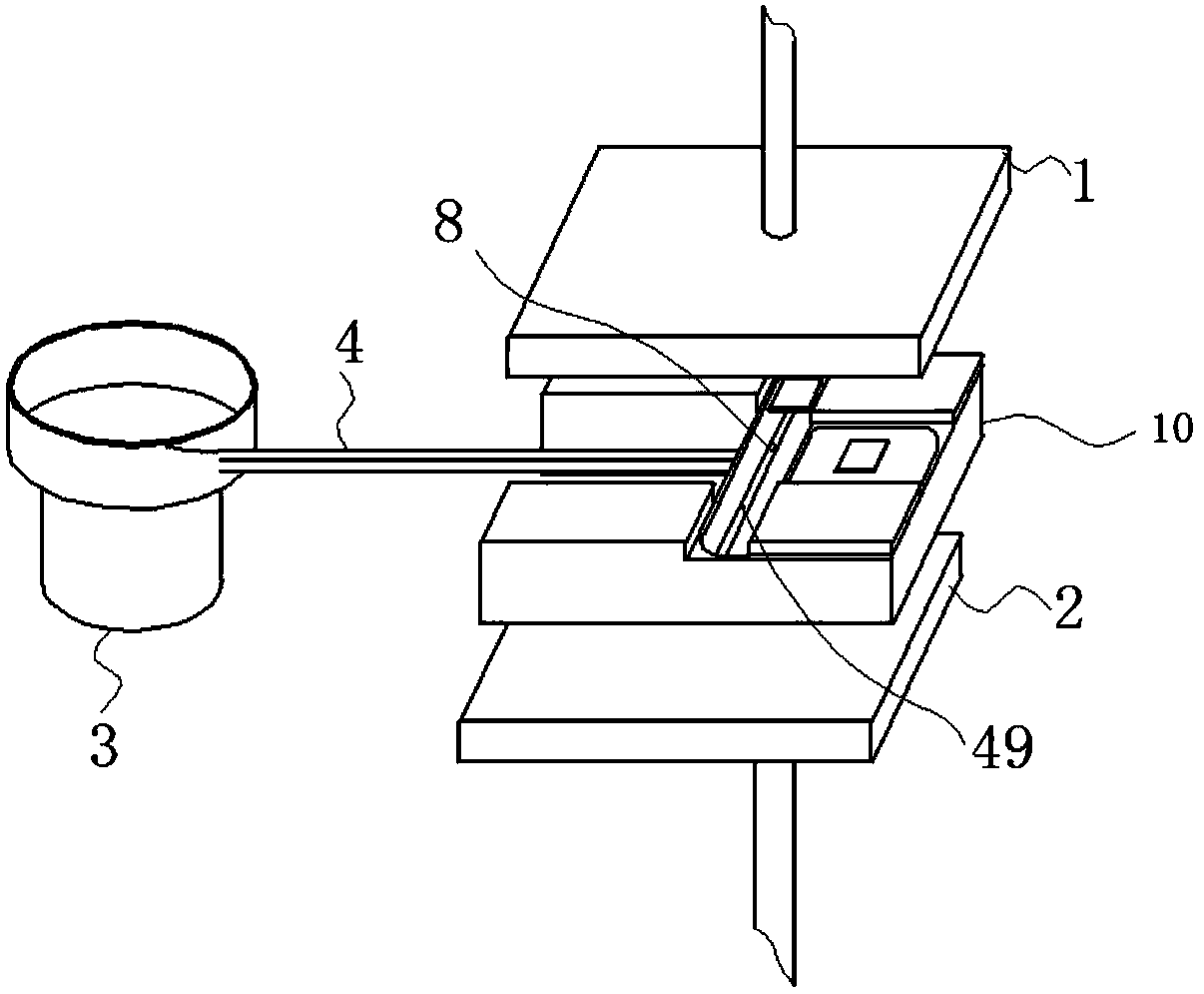
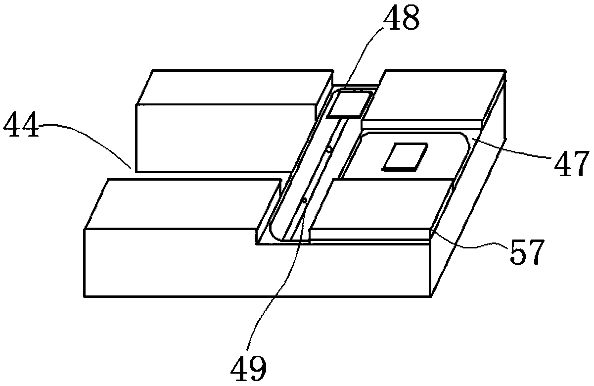
[0048] Such as figure 1 As shown, a guided stamping riveting system includes a press, a transport mold 10 arranged between the upper and lower platens of the press for transporting riveted parts, the transport mold 10 is fixedly connected to the press body via a support rod and The parts to be riveted are transported between the upper and lower platens 1 and 2 for the riveting process; one side of the press is equipped with an automatic sifting and sending silver contact mechanism, and the automatic sifting and sending silver contact mechanism will screen the qualified silver through the silver contact transportation track 4. The contact 5 is delivered to the lower end of the piece to be riveted; the piece to be riveted and the silver c...


PUM


Abstract

The invention relates to the technical field of punch riveting, in particular to an oriented punch riveting system which comprises a press and a conveying mold. The conveying mold is arranged betweenan upper press plate and a lower press plate of the press and used for conveying a workpiece to be riveted, and through riveting molds arranged on the upper press plate and the lower press plate of the press, the workpiece to be riveted is riveted with a silver contact arranged at the lower end of the workpiece to be riveted. Therefore, the oriented punch riveting system has the advantages of highautomation level, high production efficiency and low production cost; the oriented punch riveting system is provided with an automatic silver contact screening and conveying mechanism, screened silver contacts can be conveyed to the riveting molds through silver contact conveying rails automatically; the started press drives the riveting molds on the press to complete riveting of the to-be-riveted workpiece which is conveyed through the conveying mold; after the riveting process, plates can be moved along the vertical conveying rails on the conveying mold continuously and can be conveyed to designated positions; the whole process can be completed without any staff, and accordingly full-automatic production of the riveting process is achieved.

Description

Technical field: [0001] The invention relates to the technical field of stamping riveting, in particular to a guided stamping riveting system. Background technique: [0002] With the development of industry, new materials such as aluminum alloy and high-strength steel are gradually applied to all walks of life in society, and the requirements for the connection technology and process of sheet metal are also getting higher and higher. Traditional sheet metal connection methods such as spot welding, bolt connection, rivet connection, etc., have problems such as poor surface quality, easy corrosion, and even inability to achieve welding. For example, spot welding has a high temperature during the welding process, which is prone to thermal deformation and damages the original coating and decorative layer on the surface of the plate, making it difficult for the surface of the part to meet the quality requirements, and it is difficult to achieve welding of different materials such...

Claims


Application Information

Patent Timeline
IPC IPC(8): B21J15/10B21J15/32B21J15/38B21D28/02B21D43/12
CPCB21J15/10B21D28/02B21D43/12B21J15/32B21J15/38
Inventor 于海利
Owner 安徽汇精智能工业科技有限公司
Learn More