Automatic calibrating system for ultrahigh-frequency partial discharge tester and method thereof

An automatic calibration and high-frequency bureau technology, which is applied in the direction of instruments, measuring devices, and measuring electrical variables, can solve the problems of weak UHF signal frequency band energy, insufficient signal strength, and large measurement errors, so as to improve calibration work efficiency, The effect of simple control method and high calibration accuracy

Inactive Publication Date: 2018-08-07
ELECTRIC POWER RES INST OF STATE GRID ANHUI ELECTRIC POWER +1
View PDF7 Cites 3 Cited by
  • Summary
  • Abstract
  • Description
  • Claims
  • Application Information

AI Technical Summary

Problems solved by technology

At present, the most widely used is to place the sensor directly on the transformer or GIS model installed with various partial discharge defects to evaluate the detection effectiveness of the UHF partial discharge instrument, including signal-to-noise ratio, sensitivity and gain, etc., but the partial discharge The inherent differentiation of the defect model itself leads to a large dispersion of test results
The British DMA company tests the equivalent height of the sensor by

Method used


Image

  • Automatic calibrating system for ultrahigh-frequency partial discharge tester and method thereof

Examples


Embodiment 1

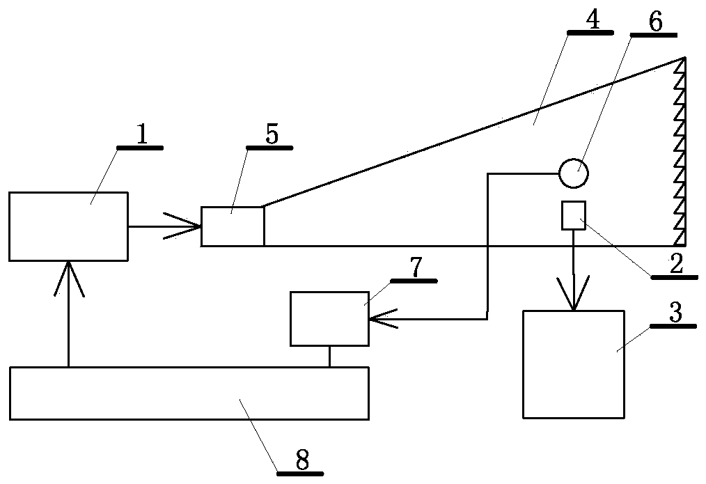
[0026] A kind of UHF partial discharge instrument automatic calibration system, see figure 1 , including a calibration signal generation 1, a UHF partial discharge sensor 2 and a calibrated UHF partial discharge instrument 3, the UHF partial discharge sensor is connected to the UHF partial discharge instrument as an accessory of the UHF partial discharge instrument, wherein the calibration The high frequency signal output of the signal generator is connected to the signal input coaxial connector 5 of a GTEM cell 4, the UHF partial discharge sensor is placed in the center of the GTEM cell, and a field strength probe 6 is arranged in the center of the GTEM cell, and the field strength probe is connected to a An oscilloscope 7 is installed outside the GTEM cell, the output signal of the oscilloscope is connected to a controller 8, and the controller is connected to control the calibration signal generator. The UHF partial discharge sensor is a reference sensor that has been certi...

Embodiment 2

[0028] An automatic calibration method for a UHF partial discharge instrument. This embodiment is an automatic calibration method based on the automatic calibration system for a UHF partial discharge instrument in Embodiment 1, so the content in Embodiment 1 should be regarded as the content of this embodiment. At the same time, the content of this embodiment should also be regarded as a supplement to the content of Embodiment 1, wherein: the system includes a calibration signal generator and a calibrated UHF partial discharge instrument, and the UHF partial discharge instrument includes a UHF partial discharge instrument. The high-frequency signal output of the calibration signal generator is connected to the signal input coaxial connector of a GTEM cell, the UHF partial discharge sensor is placed in the center of the GTEM cell, and a field strength probe is arranged in the center of the GTEM cell. Connect an oscilloscope installed outside the GTEM cell, the output signal of t...


PUM

PropertyMeasurementUnit
Diameteraaaaaaaaaa

Abstract

The invention discloses an automatic calibrating system for an ultrahigh-frequency partial discharge tester and a method thereof. The system comprises a calibrating signal generator, an UHF partial discharge sensor and a calibrated ultrahigh-frequency partial discharge tester. The ultrahigh-frequency partial discharge tester is connected with the UHF partial discharge sensor. The high-frequency signal output end of the calibrating signal generator is connected with a signal input coaxial joint of a GTEM small chamber. The UHF partial sensor is placed at the central part of the GTEM small chamber. The middle part of the GTEM small chamber is provided with a field strength probe. The field strength probe is connected with an oscilloscope which is arranged outside the GTEM small chamber. Theoutput signal of the oscilloscope is connected with a controller. The controller is connected with the calibrating signal generator. The automatic calibrating system performs real-time hardware part controlling, data acquisition and displaying processing on the ultrahigh-frequency partial discharge tester. The system has advantages of high reliability, real-time measurement and effective calibrating efficiency improvement. A feasible method is supplied for automatic calibration of the ultrahigh-frequency partial discharge tester. The automatic calibrating system further has advantages of highcalibration precision and simple control method.

Description

technical field [0001] The invention relates to an automatic calibration system and method for a UHF partial discharge instrument, which is an automatic calibration system and method for an UHF partial discharge instrument based on real-time control, data acquisition, processing and display of a C# platform. Background technique [0002] For the calibration of UHF PD instruments under laboratory conditions using UHF sensors, there is no unified evaluation standard at home and abroad, and there is no widely recognized performance test method. At present, the most widely used is to place the sensor directly on the transformer or GIS model installed with various partial discharge defects to evaluate the detection effectiveness of the UHF partial discharge instrument, including signal-to-noise ratio, sensitivity and gain, etc., but the partial discharge The inherent differentiation of the defect model itself leads to a large dispersion of test results. The British DMA company t...

Claims


Application Information

Patent Timeline
IPC IPC(8): G01R35/00
CPCG01R35/005
Inventor 秦金飞陈迪朱琦张军周玮余雪芹王旭
Owner ELECTRIC POWER RES INST OF STATE GRID ANHUI ELECTRIC POWER
Why Eureka
Try Eureka