Battery pack cooling and heating integral structure

A battery pack and topology technology, applied in the application field of new energy vehicles, can solve the problems of pipeline system equipment and manufacturing difficulties, large battery inertial load, leakage and other problems, and achieve the effect of low weight and small volume

Active Publication Date: 2018-08-07
HEFEI GUOXUAN HIGH TECH POWER ENERGY
View PDF8 Cites 3 Cited by
  • Summary
  • Abstract
  • Description
  • Claims
  • Application Information

AI Technical Summary

Problems solved by technology

[0004] However, in the complex operating environment of the vehicle, different road load excitations, low temperature to -30°C in different areas, high temperature to 60°C on the surface, and rainy days, high and low air pressure, acid-base corrosion and other environments, not only require the battery to be sealed at IP67 level Doing a good job in thermal design under the conditions also requires that the liquid cooling system with high-efficiency heat exchange does not bear large loads and cause leakage risks
[0005] At present, most of the cooling and heating piping systems in the market are placed inside the battery box. In order to ensure thermal uniformity, many piping systems are arranged at the bottom of the battery cells or modules to withstand large inertial loads of the batteries. , the complex piping system also brings difficulties to equipment and manufacturing

Method used


Image

  • Battery pack cooling and heating integral structure
  • Battery pack cooling and heating integral structure
  • Battery pack cooling and heating integral structure

Examples


Embodiment Construction

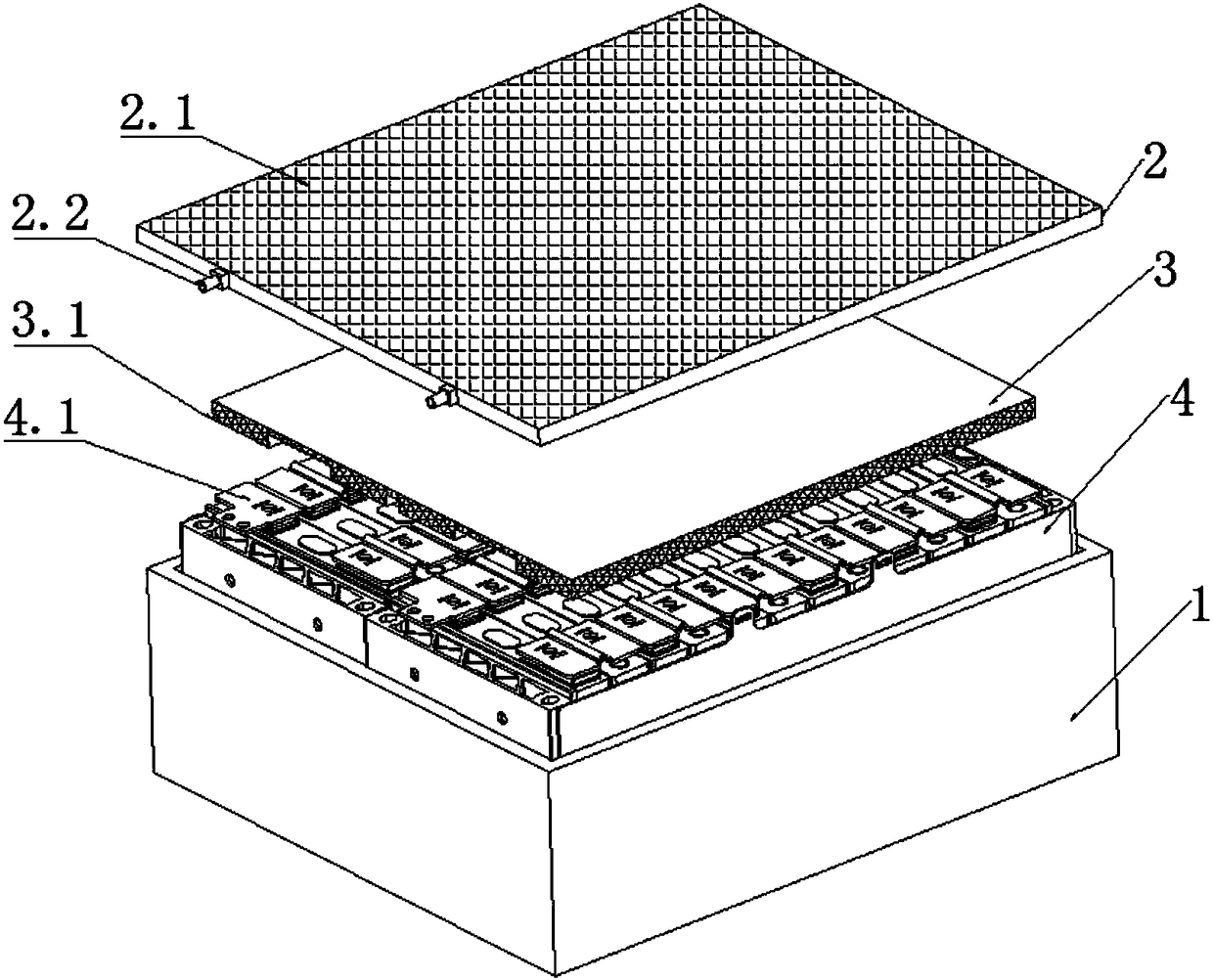
[0024] refer to figure 1 , an integrated structure for cooling and heating of the battery pack proposed by the present invention, including: a box body 1, a box cover 2, a heat transfer structure 3 and a module 4, and the heat transfer structure 3 is a heat conducting and insulating structure.

[0025] The module 4 is installed in the box body 1 so as to protect, support and fix the module 4 . The box cover 2 is covered on the box body 1 and connected with the box body 1 .

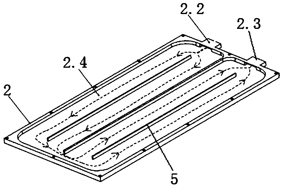
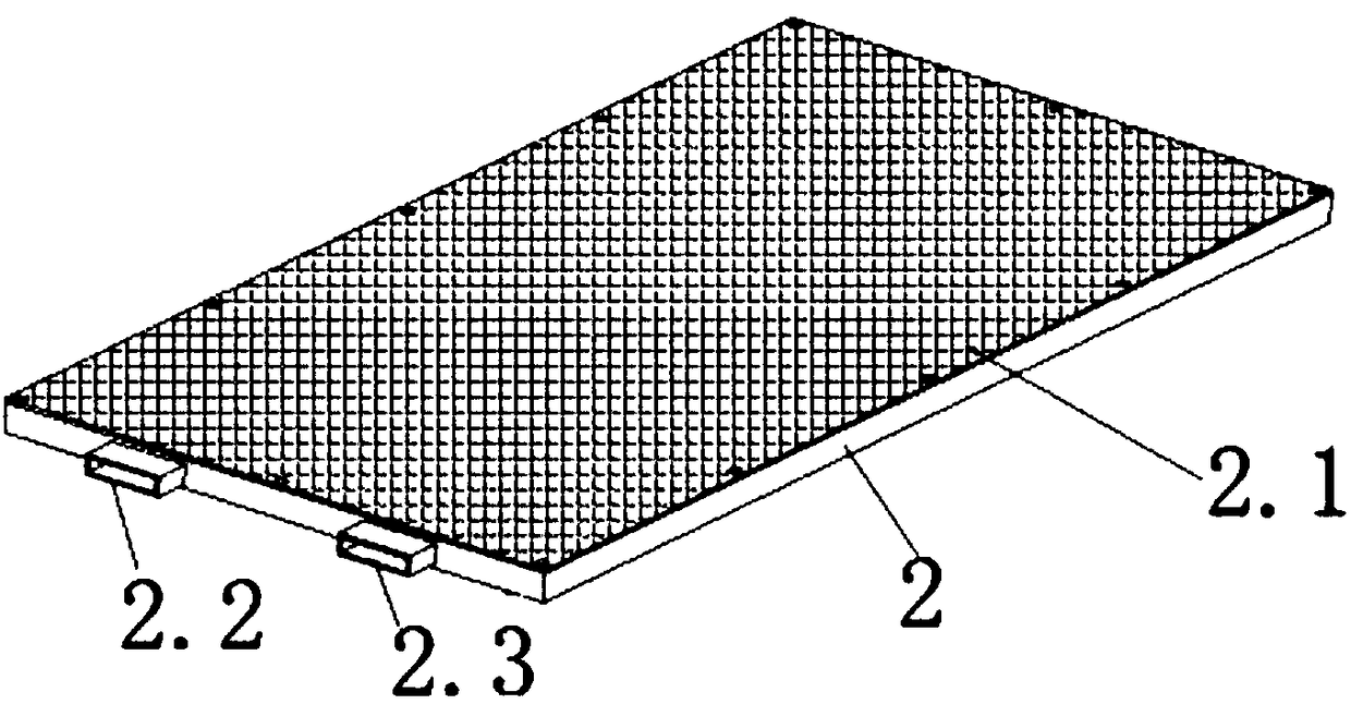
[0026] The inside of the box cover 2 is provided with a heat conduction cavity 2.4, and the heat transfer structure 3 covers the module 4 and adheres to the lower surface of the box cover 2. The side of the case cover 2 is provided with an input joint 2.2 and an output joint 2.3 communicating with the heat conduction cavity, and the input joint 2.2, the heat conduction cavity and the output joint 2.3 are sequentially connected to form a fluid delivery path. In this way, a sealed environment is formed by ...


PUM

PropertyMeasurementUnit
thicknessaaaaaaaaaa

Abstract

The invention discloses a battery pack cooling and heating integral structure. A cover and a box body form a closed environment, conduction of module temperature and temperature of fluid in a heat-conducting cavity is achieved through a heat-conducting structure, and thus, regulation of the module temperature can be achieved by filling the heat-conducting cavity with cooling liquid or heating liquid through an inlet joint and an outlet joint and further integral regulation of cooling and heating battery packs can be achieved.

Description

technical field [0001] The invention relates to the technical field of new energy vehicle applications, in particular to an integrated structure for cooling and heating a battery pack. Background technique [0002] As a modern industrial product that promotes human civilization, automobiles not only bring convenience to human life, but also bring great environmental pollution. With the increasing shortage of traditional fossil energy, especially the limitation of non-renewable resources such as oil, people are turning more attention to new energy vehicles. Electric vehicles have environmental advantages such as high efficiency, energy saving, low noise, and zero emissions, which cannot be compared with traditional fuel vehicles, and have become a hot research topic at this stage. [0003] However, the power battery system, as the core component of the battery car, will be accompanied by a large amount of heat generation during charging and discharging. Work in the temperat...

Claims


Application Information

Patent Timeline
Patent Type & Authority Applications(China)
IPC IPC(8): H01M10/613H01M10/615H01M10/625H01M10/6554H01M10/6567
CPCH01M10/613H01M10/615H01M10/625H01M10/6554H01M10/6567Y02E60/10
Inventor 胡为松
Owner HEFEI GUOXUAN HIGH TECH POWER ENERGY
Why Eureka
Try Eureka