
Conductor temperature measurement type T-shaped cable joint device

A technology of cable joints and receiving devices, which is applied in the direction of measuring devices, electrical devices, and parts of connecting devices. It can solve problems such as very high requirements for stability and maintenance-free, signal penetration, and difficulties, so as to improve monitoring The effect of reliability and durability

Pending Publication Date: 2018-08-07
JIANGSU ELECTRIC POWER CO +1
View PDF0 Cites 4 Cited by
  • Summary
  • Abstract
  • Description
  • Claims
  • Application Information

AI Technical Summary

Problems solved by technology

Therefore, how to directly measure the operating temperature of the conductor is very critical and important for the transportation inspection department, but there are still many difficulties, such as how to let the signal penetrate the insulation and shielding layer, which is still relatively difficult in terms of current technical means. At the same time, because the sensor is required to be completely covered in the insulating layer, the requirements for stability and maintenance-free are very high

Method used


Image

  • Conductor temperature measurement type T-shaped cable joint device
  • Conductor temperature measurement type T-shaped cable joint device
  • Conductor temperature measurement type T-shaped cable joint device

Examples


Embodiment Construction

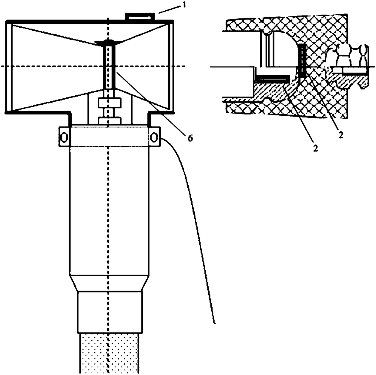
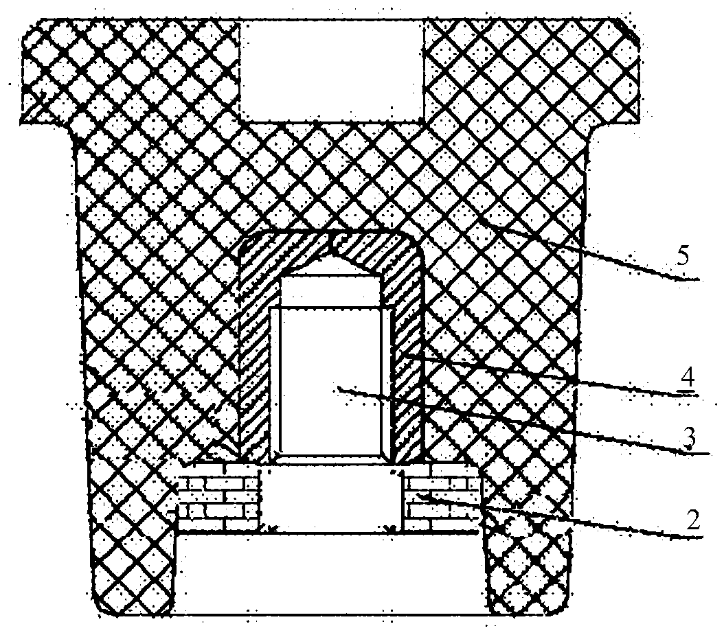
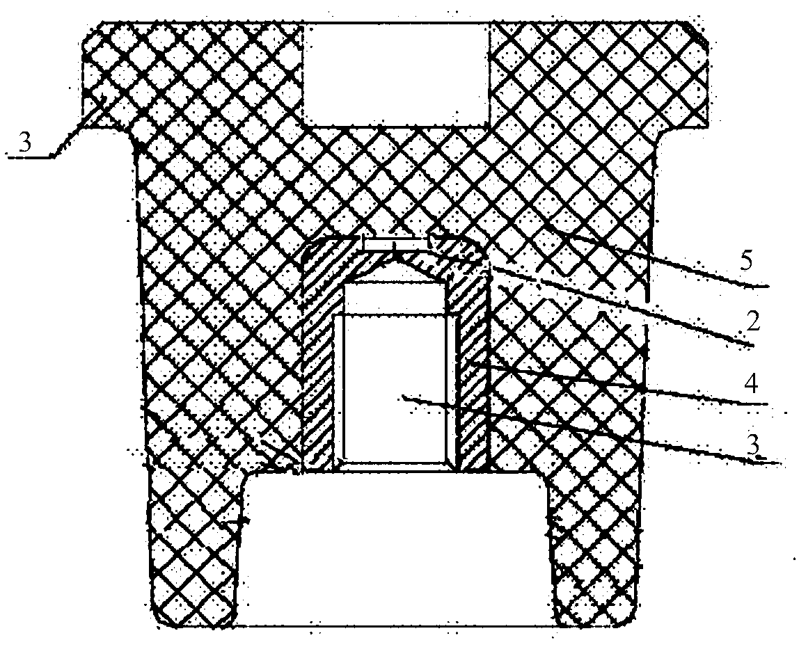
[0017] figure 1 It is the position diagram of temperature measuring type T-joint sensor and receiving device. The external receiving device 1 is placed outside the body of the T-shaped joint, and placed in a concentric circle with the built-in sensor 2 . The placement position of the built-in sensor 2 is related to the internal design of the T-joint. When there is a gap in the cavity surrounded by the conductor terminal 6 and the metal insert 4, the built-in sensor 2 can be placed on the inner wall of the metal insert 4. For the placement method, see figure 2 mentioned. When there is no gap in the cavity surrounded by the conductor terminal 6 and the metal insert 4, it can only be placed at the tail 5 of the metal insert 4. For the placement method, see image 3 .

[0018] figure 2 The built-in sensor 2 is placed on the inner wall of the metal insert 4. After the product is installed, the conductor terminal 6 will be closely combined with the metal insert 4. Only when t...


PUM


Abstract

The invention discloses a conductor temperature measurement type T-shaped cable joint device, and belongs to the field of power equipment monitoring. The device comprises a sensor and an external temperature display device, wherein the sensor and the external temperature display device are tightly attached to the conductor terminal of a T-shaped cable joint or are connected with the surface of themetal body of a tail plug connected with the conductor terminal of the T-shaped cable joint. The sensor installed inside the connector does not use a battery and does not need to be maintained. The sensor is integrally located in a conductor equipotential body and does not have negative influence on the design of the electric field of the T-shaped cable joint. The sensor and the T-shaped cable joint can work for a long time during the whole service life. By monitoring the temperature of the point, poor connection between the terminal of the T-shaped cable joint and equipment can be found in time. Corresponding alarm temperature can be set, and further faults can be avoided. Data in the whole operation period can be collected, the load condition of the whole loop can be monitored, and a basis can be provided for adjustment of loads.

Description

technical field [0001] The invention belongs to the field of temperature measurement of cable joints in electric equipment, and in particular relates to a cable joint device for real-time monitoring of the temperature of cable conductors. Background technique [0002] With the rapid development of the economy, the demand for electricity is also increasing. The production and life of modern society are inseparable from the demand for electricity at all times. At the same time, every failure of the power grid will disrupt the production and life of the normal society, so the safe operation of the power grid is of great importance. The operating temperature of the equipment is an important parameter to investigate the safe operation of the primary equipment, so the direct temperature monitoring of the power equipment has very important value. [0003] In the power system, the current is mainly transmitted through the conductor, which is the source of heat generation. Most of t...

Claims


Application Information

Patent Timeline
Patent Type & Authority Applications(China)
IPC IPC(8): H01R13/66G01K7/34
CPCH01R13/6683G01K7/34
Inventor 徐勇黄振勇高晓宁陈吉洋孙叶旭濮实徐俊
Owner JIANGSU ELECTRIC POWER CO
Learn More