Shaft workpiece alignment device and alignment method thereof

A technology for shaft workpieces and components, which is applied in the field of aligning devices for shaft workpieces, can solve the problems of easy deviation, low precision, troublesome operation, etc., and achieve the effects of convenient alignment, high precision, and convenient installation

Inactive Publication Date: 2018-08-10
CHANGZHOU COLLEGE OF INFORMATION TECH
View PDF0 Cites 2 Cited by
  • Summary
  • Abstract
  • Description
  • Claims
  • Application Information

AI Technical Summary

Problems solved by technology

Generally, we use V-shaped blocks or dial indicators to achieve such work. The operation is extremely troublesome, the efficiency is low, the accuracy is not high, and deviations are easy to occur, and the quick-installation fixture is only suitable for mass production.

Method used


Image

  • Shaft workpiece alignment device and alignment method thereof
  • Shaft workpiece alignment device and alignment method thereof
  • Shaft workpiece alignment device and alignment method thereof

Examples


Embodiment 1

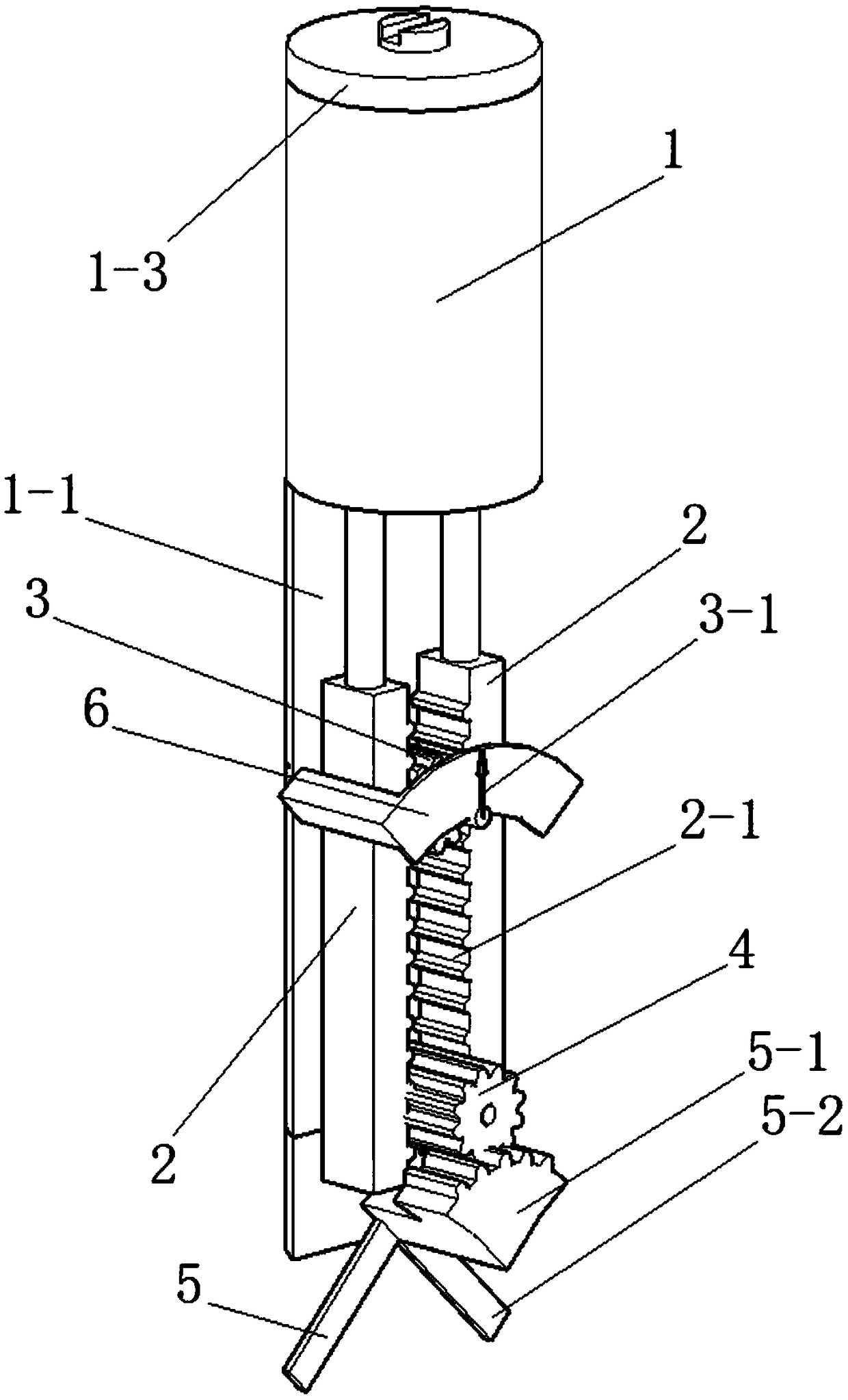
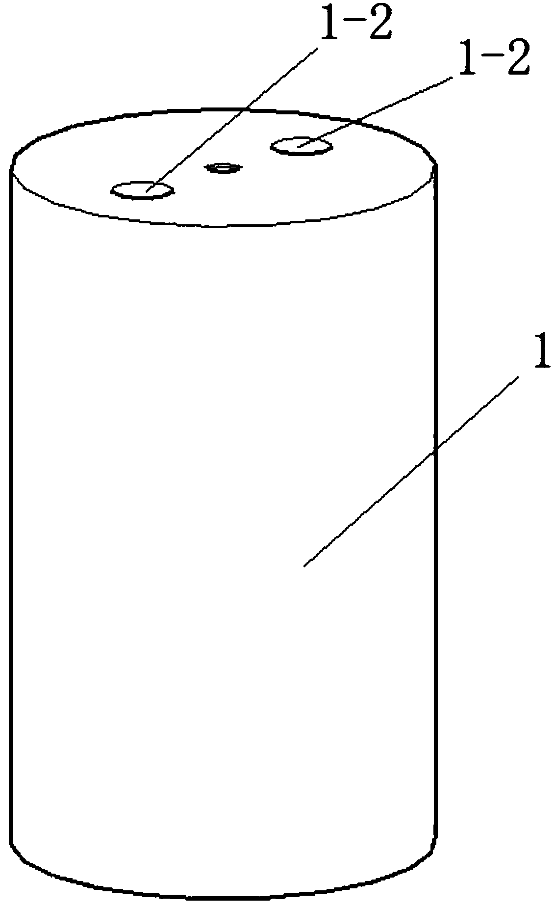
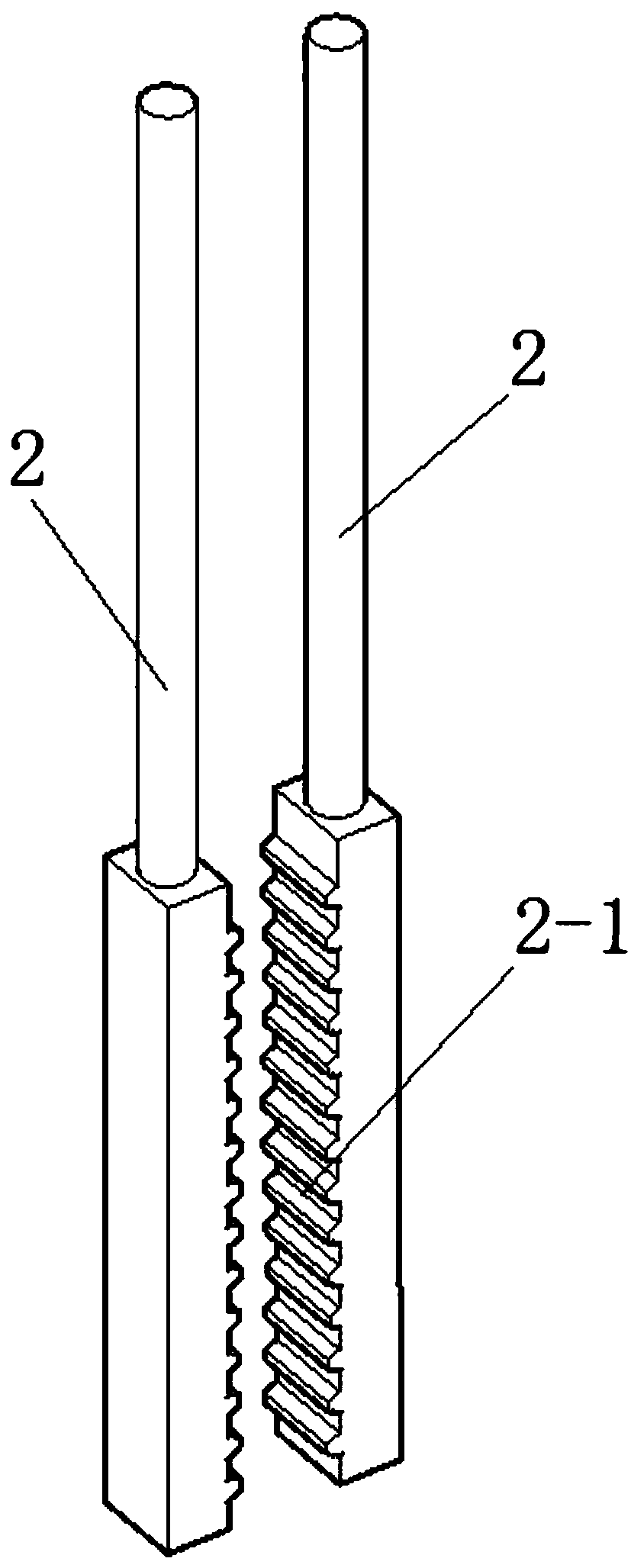
[0033] See Figure 1 to Figure 4 , The alignment device for shaft workpieces in this embodiment includes a fixed seat 1, a balance bar 2, a pointer gear 3, an input gear 4, a measuring claw assembly 5 and a scale plate 6.

[0034] A back plate 1-1 extending downward is provided on the fixing base 1 . Two balance poles 2 are arranged in parallel. The tops of the two balance poles 2 protrude into the fixed seat 1 and are slidably connected with the fixed seat 1 . The bottoms of the two balance bars 2 are fixed with racks 2-1 with opposite tooth surfaces. Both the pointer gear 3 and the input gear 4 are rotatably arranged on the back plate 1-1, and are both meshed with the two racks 2-1. The input gear 4 is located below the pointer gear 3 . The diameter and modulus of the pointer gear 3 and the input gear 4 are consistent. A pointer 3-1 is fixed at the center of the front end of the pointer gear 3. The measuring jaw assembly 5 drives the input gear 4 to rotate. The scale ...


PUM


Abstract

The invention discloses a shaft workpiece alignment device and an alignment method of the shaft workpiece alignment device. The shaft workpiece alignment device comprises a fixing base, balancing rods, a pointer gear, an input gear, a measuring claw assembly and a scale plate. A back plate which downwards extends is arranged on the fixing base. The two balancing rods are arranged in parallel, andthe tops of the two balancing rods stretch into the fixing base and are connected with the fixing base in a sliding mode. Racks are fixedly arranged at the bottoms of the two balancing rods, and the tooth surfaces of the racks are arranged in a face-to-face mode. The pointer gear and the input gear are arranged on the back plate in a rotating mode and mesh with the two racks. The input gear is located below the pointer gear. The diameters of the pointer gear and the input gear are equal, and the moduli of the pointer gear and the input gear are equal. A pointer is fixedly arranged in the center of the front end face of the pointer gear. The measuring claw assembly drives the input gear to rotate. The shaft workpiece alignment device is ingenious in structure, high in accuracy and convenient to use, rapid alignment of the cylindrical axis of a shaft workpiece is achieved, the operation working procedure is simplified, and the production quality and the production efficiency are improved.

Description

technical field [0001] The invention relates to a straightening device for a shaft workpiece and a straightening method thereof. Background technique [0002] When milling the keyway on the shaft or performing radial drilling on the shaft, it is necessary to use a measuring tool to find the highest point of the outer circle of the shaft, and the fundamental purpose is to make the clamping position of the shaft workpiece between the axis of the machine tool spindle and the The position where the cylinder axes of shaft workpieces intersect, so as to meet the process requirements. Generally, we use V-shaped blocks or dial indicators to achieve such work. The operation is extremely troublesome, the efficiency is low, the accuracy is not high, and deviations are easy to occur, and the quick-installation fixture is only suitable for mass production. Therefore, it is necessary to design a shaft workpiece alignment device and alignment method thereof with high precision, high work ...

Claims


Application Information

Patent Timeline
IPC IPC(8): B23Q3/06
CPCB23Q3/06B23Q3/062
Inventor 陆冯刘海兰
Owner CHANGZHOU COLLEGE OF INFORMATION TECH
Why Eureka
Try Eureka