Supercharge Your Innovation With Domain-Expert AI Agents!

Copper foil power source structure convenient to maintain

A technology of power supply and copper foil, applied in electroforming, electrolysis process, electrolysis components, etc., can solve the problems of space distribution and inconvenient maintenance and operation, and achieve the effect of compact structure, reduced consumption and reasonable power supply

Pending Publication Date: 2018-08-10
GUANGZHOU QINGTIAN INDAL
View PDF3 Cites 0 Cited by
  • Summary
  • Abstract
  • Description
  • Claims
  • Application Information

AI Technical Summary

Problems solved by technology

Therefore, the electrical connection structure between the copper foil rectifier power supply and the foil machine in the prior art is very inconvenient for the spatial distribution and maintenance operations around the entire foil machine

Method used


Image

  • Copper foil power source structure convenient to maintain
  • Copper foil power source structure convenient to maintain
  • Copper foil power source structure convenient to maintain

Examples


Embodiment 1

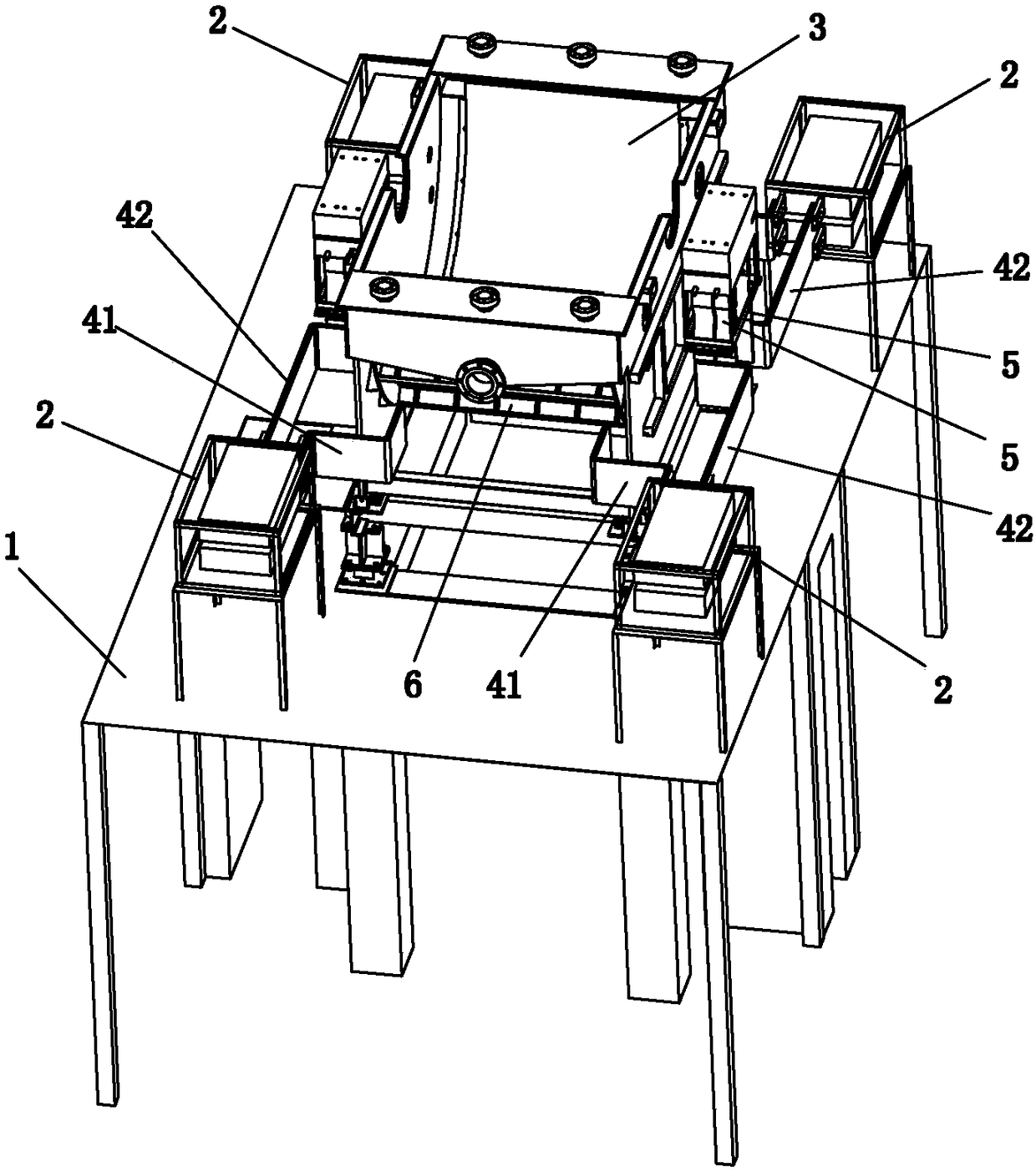
[0025] like figure 1 Shown is embodiment one ( figure 1 Cathode roller 7 is not shown in the drawing), the foil machine 3 is installed on the foil machine platform 1, the foil machine platform 1 is supported by the pillars below it, and the opposite sides of the foil machine 3 are provided for connecting with the cathode roller. 7 is connected to the electrical connection terminal 5, and the anode plate 6 is located on the other two opposite sides. The power structure includes four power modules 2 .

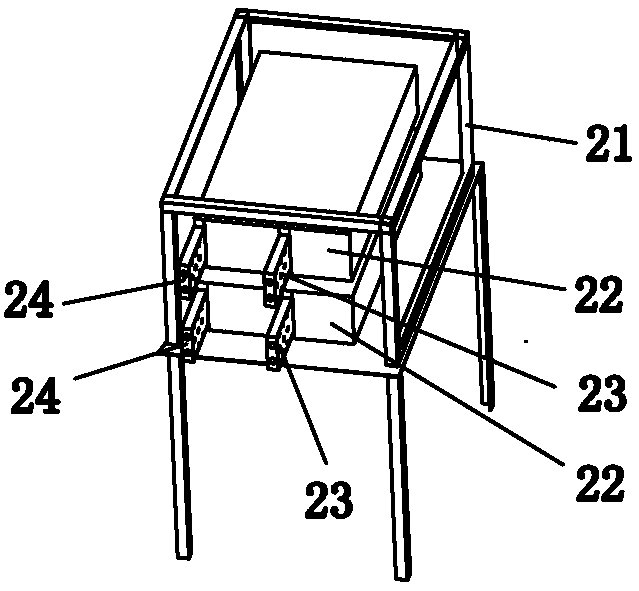
[0026] like figure 2 As shown, the power supply module 2 includes a bracket 21 and two power stand-alone units 22. The support 21 is a rectangular frame for encapsulating or supporting the power supply stand-alone unit. Stacked, the control terminal and core components of the power stand-alone unit 22 are located on the side facing the outside. The weight of the stand-alone power supply 22 is about tens of kilograms. In order to facilitate maintenance and installation, the s...

Embodiment 2

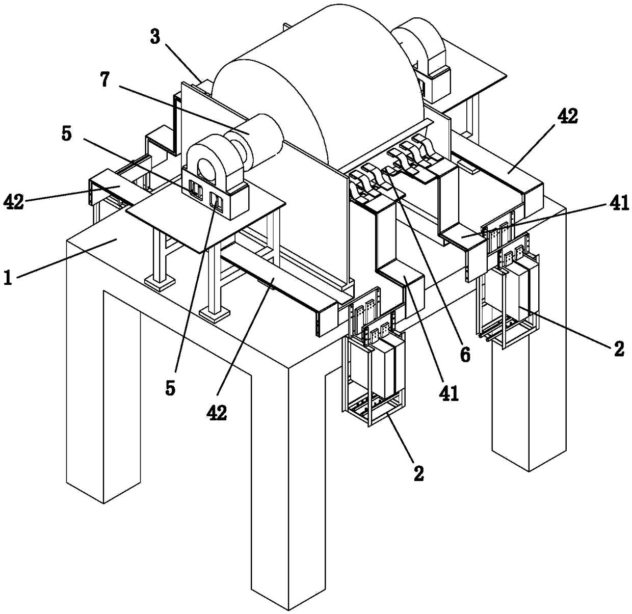
[0030] like image 3 Shown is the second embodiment, the foil machine 3 is also installed on the foil machine platform 1, and the foil machine platform 1 is supported by the pillars below it. The power supply structure also includes four power supply modules 2 .

[0031] like Figure 4 As shown, the power supply module 2 includes a bracket 21 and two power stand-alone units 22, the power stand-alone unit 22 is vertically installed in the support 21, and the two power supply unit 22 are distributed correspondingly on the left and right, and the control terminal and core components of the power unit 22 are located below. Both the positive pole 24 and the negative pole 23 of the stand-alone power supply 22 are located on the vertically upward side of the bracket 21, and the negative pole 23 is longer than the positive pole 24, so that the positive pole and the negative pole are staggered from each other, leaving enough maintenance space, so that the connection of the positive po...


PUM


Abstract

The invention discloses a copper foil power source structure convenient to maintain. The power source structure comprises four power modules. Each power module comprises at least one power source single machine and a support for packaging or supporting the power source single machines. The four power modules are distributed in the four corner areas of a foil generation machine and are fixed to thefour corner areas of the foil generation machine through the respective supports. The positive electrode and the negative electrode of each power module are output on the same side of the module. Thepositive electrode output end of each power source single machine in each power module is connected to an adjacent foil generation machine anode plate, and the negative electrode output end of each power source single machine of each power module is connected to an adjacent foil generation machine cathode roller. The copper foil power source structure is compact in structure, convenient to install and maintain, simple in connection and small in usage amount.

Description

technical field [0001] The invention relates to a rectifying power supply structure, in particular to a copper foil power supply structure which is easy to maintain. Background technique [0002] With the development of lithium-ion batteries and printed circuit boards in China, the domestic demand for copper foil is getting higher and higher. At present, the production equipment of copper foil generally includes a foil machine, a copper foil rectifier power supply (such as a thyristor rectifier power supply, a high-frequency switching power supply) and a cooling system. The foil machine is mainly composed of eight parts: cathode roller, anode tank, anode plate, liquid inlet system, polishing system, spray system, winding system and electric control system. The negative pole of the copper foil rectifier power supply is connected to the cathode roll of the foil machine, and the positive pole of the copper foil rectifier power supply is connected to the anode plate of the foil...

Claims


Application Information

Patent Timeline
Patent Type & Authority Applications(China)
IPC IPC(8): C25D1/04C25D17/00
CPCC25D1/04C25D17/00C25D17/007
Inventor 刘柱龙蔡小纯王浩龙丁小松罗小强陈兆循
Owner GUANGZHOU QINGTIAN INDAL
Features
  • R&D
  • Intellectual Property
  • Life Sciences
  • Materials
  • Tech Scout
  • Unparalleled Data Quality
  • Higher Quality Content
  • 60% Fewer Hallucinations
Learn More