IGBT overcurrent detection device based on active clamp feedback type and IGBT overcurrent detection method based on active clamp feedback type

A technology of overcurrent detection and detection circuit, which is applied in the direction of measuring devices, measuring electrical variables, bipolar transistor testing, etc., can solve problems affecting system reliability, detection time delay, heat loss, etc., and achieves easy fault analysis and improvement Reliability, detection comprehensive and effective

Active Publication Date: 2018-08-10
CHINA UNIV OF MINING & TECH
View PDF9 Cites 16 Cited by
  • Summary
  • Abstract
  • Description
  • Claims
  • Application Information

AI Technical Summary

Problems solved by technology

It is frequently broken down in a short period of time, and it also faces the problem of heat loss, which affects the reliability of the system
Although the third method can detect the system overcurrent, it cannot identify the overcur

Method used


Image

  • IGBT overcurrent detection device based on active clamp feedback type and IGBT overcurrent detection method based on active clamp feedback type
  • IGBT overcurrent detection device based on active clamp feedback type and IGBT overcurrent detection method based on active clamp feedback type
  • IGBT overcurrent detection device based on active clamp feedback type and IGBT overcurrent detection method based on active clamp feedback type

Examples


Embodiment 1

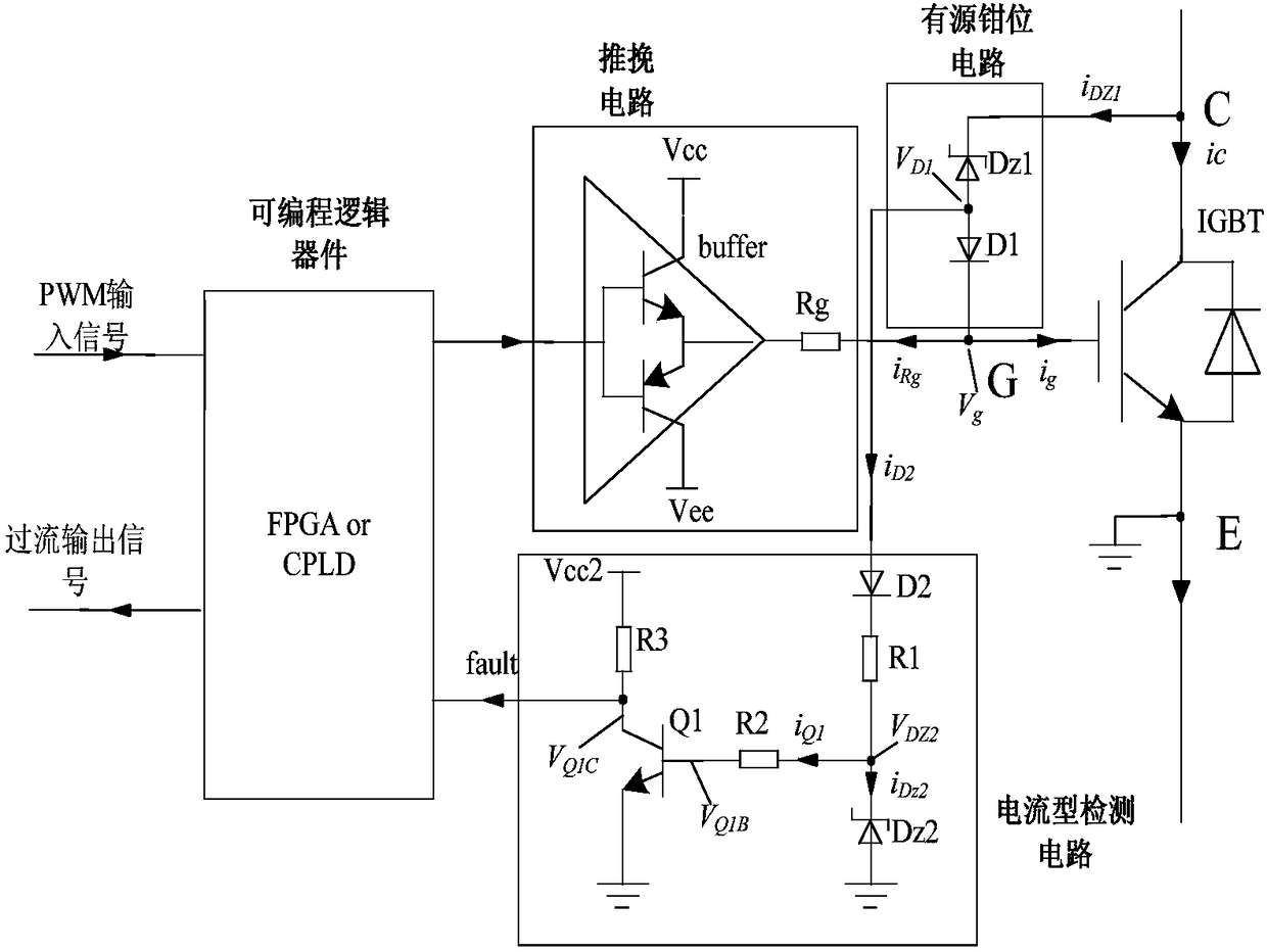
[0031] Embodiment 1: The detection circuit of this embodiment is based on a current signal, and the current detection circuit is composed of 3 resistors, 2 diodes and 1 triode. Such as figure 2 The anode of the shown diode D2 is connected to the anode of D1 in the active clamp circuit, the cathode of the diode D2 is connected to one end of the resistor R1, the other end of the resistor R1 is connected to the cathode of the Zener diode Dz2, and the anode of the Zener diode Dz2 is connected to the reference ground . At the same time, the cathode of the regulator diode Dz2 is connected to one end of the resistor R2, the other end of the resistor R2 is connected to the base of the transistor Q1, the emitter of the transistor Q1 is grounded, one end of the collector of the transistor Q1 is connected to one end of the resistor R3, and the other end of the resistor R3 One end is connected to the power supply Vcc2. The collector of the transistor Q1 is connected to the input port o...

Embodiment 2

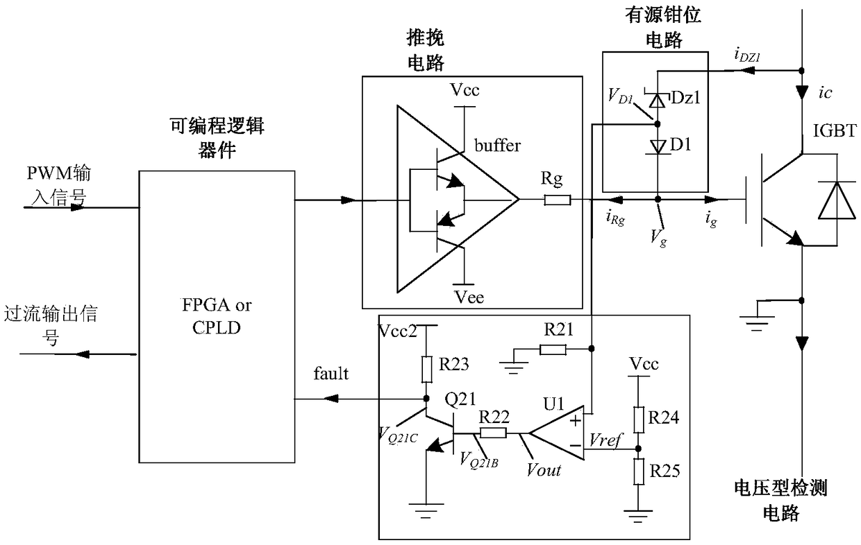
[0037] Embodiment 2: The detection circuit of this embodiment is based on a voltage signal, and the working principle of other circuits is the same as that of Embodiment 1. The voltage detection circuit is composed of 5 resistors, 1 comparator and 1 triode. The positive input terminal of the comparator U1 is respectively connected to one end of the resistor R21 and the anode of the diode D1 in the active clamping circuit; the other end of the resistor R21 is grounded, and the comparison The reverse input terminal of the comparator U1 is respectively connected to one end of the resistors R24 and R25; the other end of the resistor R24 ​​is connected to the power supply Vcc2, and the other end of the resistor R25 is grounded; the output terminal of the comparator U1 is connected to the resistor R22; the other end of the resistor R22 is connected to the transistor Q21 The base and the emitter of the transistor Q21 are grounded, and one end of the collector of the transistor Q21 is ...

Embodiment 3

[0042] Embodiment 3: Corresponding to Embodiment 1 and 2, this embodiment also provides an IGBT overcurrent detection method based on active clamp feedback type, which mainly includes:

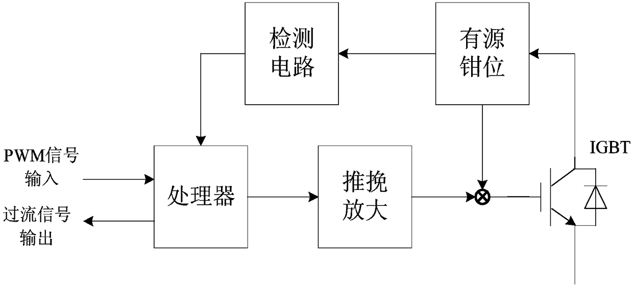
[0043] When the IGBT is over-current, that is, when the voltage across the IGBT exceeds the breakdown voltage of the active clamp diode, the active clamp circuit works to clamp the IGBT at the protection voltage; the detection circuit effectively extracts the active clamp action The time when the TVS branch current flows or the time when the clamping voltage exists, and the time signal is transmitted to the processor circuit; the processor counts and counts the time and times of the signal transmitted by the detection circuit; when the processor circuit receives When the time signal of the current flowing through the TVS branch or the time signal of the clamp voltage exceeds the system setting time, it can be determined that the IGBT has an overcurrent fault.

[0044] Among them, the system se...


PUM


Abstract

The invention provides an IGBT overcurrent detection method based on the active clamp feedback type. The method comprises the steps that the IGBT is disconnected and the voltage peak appears when overcurrent appears in the IGBT, and the active clamp circuit works to clamp the IGBT on the protection voltage when the voltage of the two ends of the IGBT exceeds the breakdown voltage of the active clamp diode; the detection circuit effectively extracts the time of TVS branch current flowing or the time of the clamp voltage in case of active clamp actuation and transmits the time signal to the processor circuit; the processor performs statistics of the time and the frequency of the signal transmitted by the detection circuit; and the judgment result indicates the overcurrent fault of the IGBT when the time signal of TVS branch current flowing or the time signal of the clamp voltage received by the processor circuit exceeds the system setting time. The invention also provides an IGBT overcurrent detection device based on the active clamp feedback type.

Description

technical field [0001] The invention belongs to the technical field of power electronics, and in particular relates to an active clamp feedback type IGBT overcurrent detection device and method. Background technique [0002] Insulated Gate Bipolar Transistor (Insulated Gate Bipolar Transistor) IGBT is widely used in power electronic circuit devices. In high-voltage and high-power applications, IGBTs often bear relatively large currents, and IGBT overcurrent is an important cause of IGBT device damage. In practical applications, due to load overload, external interference, internal signal errors and other reasons, the current of the IGBT device will increase sharply and exceed its capacity limit. At this time, the IGBT device needs to be turned off for protection to prevent the IGBT from being damaged by overheating. [0003] At present, there are three main methods for overcurrent detection of IGBT devices: [0004] 1. Desaturation detection method: by means of the relatio...

Claims


Application Information

Patent Timeline
IPC IPC(8): G01R31/26G01R19/165H03K17/082H03K17/567
CPCG01R19/165G01R31/2608H03K17/0828H03K17/567H03K2217/0027
Inventor 何凤有耿程飞张经纬王强
Owner CHINA UNIV OF MINING & TECH
Why Eureka
Try Eureka