Resonant asynchronous motor and its control method

A technology for asynchronous motors and control methods, applied in motor control, motor generator control, asynchronous induction motors, etc., can solve the problems of low efficiency, low motor efficiency and power factor, etc., to reduce eddy current loss, improve utilization, Extremely high dynamic response quality effects

Active Publication Date: 2020-01-31
TONGJI UNIV
View PDF1 Cites 0 Cited by
  • Summary
  • Abstract
  • Description
  • Claims
  • Application Information

AI Technical Summary

Problems solved by technology

[0003] The induction excitation method transmits electric energy based on the principle of electromagnetic induction, represented by AC induction motors, the rotor windings / guide bars are short-circuited, and a specific form of current is injected into the stator coil to form a magnetic field and induce the excitation current at the rotor end depending on the speed difference between the stator and the rotor. The obvious disadvantage of the induction excitation method is that the efficiency is low, and it is necessary to inject a current in a specific direction for the excitation on the stator side, resulting in relatively low efficiency and power factor of the motor using the induction excitation method

Method used


Image

  • Resonant asynchronous motor and its control method
  • Resonant asynchronous motor and its control method
  • Resonant asynchronous motor and its control method

Examples


Embodiment 1

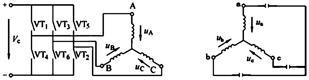
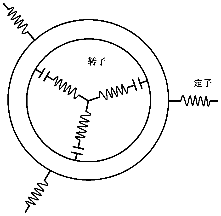
[0037] Such as figure 1 and figure 2 As shown, in the resonant asynchronous motor of this embodiment, the stator winding and the rotor winding are both provided with three phases, and the three phases of the rotor winding are symmetrical and have a 120° space (electrical) angle difference. Due to the existence of the space angle difference of the rotor winding, according to electromechanical The principle is easy to know, when there is current passing through the rotor, an equivalent space current vector can be formed.

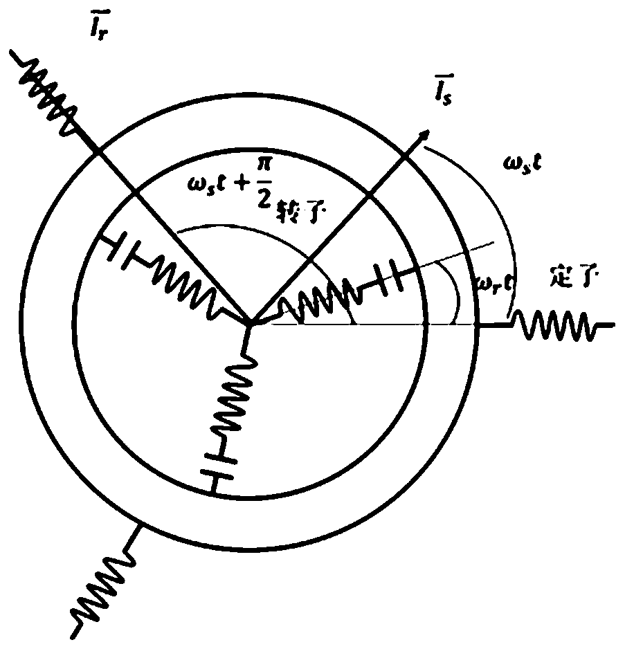
[0038] Assuming that the air-gap magnetic field is sinusoidally distributed, the current in the stator coil can be represented by a vector. When the stator three-phase current is injected according to the sinusoidal law, the current vector rotates in space. The specific method is: control the stator three-phase current I 4 (t), I B (t), I C (t) In the case of steady state, it is a symmetrical AC, that is, the amplitude of each current is the same, and the...

Embodiment 2

[0055] In the resonant asynchronous motor of this embodiment, the rotor winding is set as a two-phase LC resonant winding, which are called d and q windings respectively. The two windings are independent and orthogonal to each other. The topology is as follows: Figure 4 shown. Due to the existence of the space angle difference between the two windings, when there is current passing through the two windings, a changing space current vector can be formed.

[0056] The stator structure and stator current control method in this example are consistent with those in Embodiment 1.

[0057] The electrical characteristics of the motor are analyzed below, see Figure 5 marked. Secondary factors such as saturation and current harmonics are ignored in the following analysis.

[0058] The stator current is the same as that in Embodiment 1 and will not be repeated here.

[0059] The dq coordinate system is a coordinate system fixed to the rotor, and the d-axis direction and the q-axis ...

Embodiment 3

[0083] The resonant asynchronous motor in this embodiment is provided with an auxiliary excitation circuit / device to improve the output characteristics of the motor. Combined with the design of the rotor with two orthogonal coils, the analysis is carried out.

[0084] This embodiment is mainly considered from two perspectives, one is the current form of the two coils of the rotor, and the other is to determine the control method of the rotor end according to the current form required by the above rotor coils.

[0085] The following is discussed in conjunction with the design of the non-contact MCR-WPT, and the principle of the contact type is similar to this.

[0086] 1) Rotor target current equation

[0087] It is set that there are two coils on the physical dq axis of the rotor, such as Figure 6 As shown, the currents of the two coils are respectively:

[0088] I d (t)=I r cos(ω 0 t)

[0089]

[0090] The current of the two coils can be synthesized into a current ...


PUM


Abstract

The invention relates to a resonant asynchronous motor and a control method thereof. The resonant asynchronous motor comprises a stator winding and at least two phases of rotor windings; the rotor windings are set with determined space phase difference; the resonant asynchronous motor is characterized by also comprising resonant energy storage elements; the rotor windings and the corresponding resonant energy storage elements are electrically connected to form resonant circuits; the relative error of the resonant frequencies of the resonant circuits is less than 50%; by virtue of setting of anauxiliary exciting circuit, the motor output characteristic can be further improved; and the relative error of the exciting voltage frequency of the auxiliary exciting circuit and the resonant frequencies of the resonant circuits is less than or equal to 25%. According to the control method, each resonant circuit can work in a quasi-resonant state or a resonant state by controlling the frequencydifference between the current alternating frequency of the stator winding and the current alternating frequency of the stator winding. Compared with the prior art, the resonant asynchronous motor hasthe advantages of simple and reliable structure, low speed and high torque density, extremely high torque dynamic response and the like.

Description

technical field [0001] The invention relates to the technical field of motors and controls, in particular to a resonant asynchronous motor and a control method thereof. Background technique [0002] At present, in addition to the permanent magnet excitation method, there are mainly two methods for external excitation of the motor rotor magnetic field, namely induction excitation and electric excitation. [0003] The induction excitation method transmits electric energy based on the principle of electromagnetic induction, represented by AC induction motors, the rotor windings / guide bars are short-circuited, and a specific form of current is injected into the stator coil to form a magnetic field and induce the excitation current at the rotor end depending on the speed difference between the stator and the rotor. The obvious disadvantage of the induction excitation method is that the efficiency is low, and it needs to inject a specific direction current for the excitation on th...

Claims


Application Information

Patent Timeline
IPC IPC(8): H02K17/12H02K17/30H02K3/04H02K3/28H02P21/22H02P25/02
CPCH02K3/04H02K3/28H02K17/12H02K17/30H02K2213/03H02P21/22H02P25/02H02P2207/01
Inventor 钟再敏秦一进胡程宇
Owner TONGJI UNIV
Why Eureka
Try Eureka