LED detection device, detection system and detection method

A detection system and detection device technology, applied in lighting devices, light sources, electrical components, etc., can solve the problems of small application range of LED backlight working conditions, achieve effective reference indicators, expand application scope, and overcome limitations.

Active Publication Date: 2021-01-22
BOE TECH GRP CO LTD
View PDF4 Cites 0 Cited by
  • Summary
  • Abstract
  • Description
  • Claims
  • Application Information

AI Technical Summary

Problems solved by technology

[0005] Aiming at the shortcomings of the existing methods, the present invention proposes an LED detection device, a detection system and a detection method to solve the problem in the prior art that the application range is small when detecting the working state of the LED backlight

Method used


Image

  • LED detection device, detection system and detection method
  • LED detection device, detection system and detection method
  • LED detection device, detection system and detection method

Examples


Embodiment 1

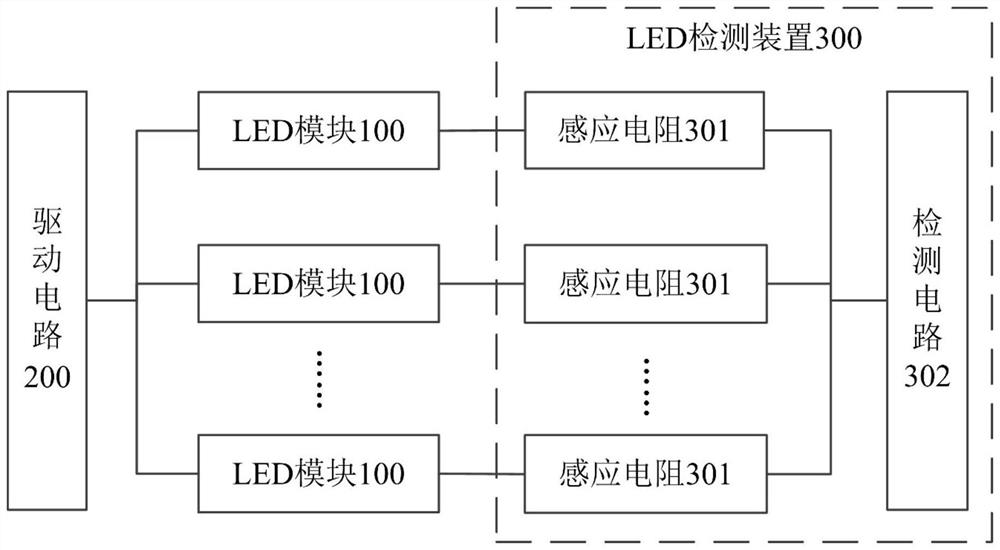
[0046] In order to solve the problem in the prior art that the working state of the LED cannot be detected in time or the application range is small, Embodiment 1 of the present invention provides an LED detection device, figure 1 A schematic frame diagram showing the structure of the detection device and its connection relationship with the LED module and the driving circuit outside the device, the detection device is used to detect the backlight working state of at least one LED module 100, and the LED module 100 can be controlled by the driving circuit 200 drives. Such as figure 1 As shown, the LED detection device 300 includes at least one sensing resistor 301 and a detection circuit 302 .

[0047] Each LED module 100 is electrically connected to a corresponding sensing resistor 301 , and the detection circuit 302 is electrically connected to each sensing resistor 301 .

[0048] The detection circuit 302 is used to detect the induced current of each sensing resistor 301 ...

Embodiment 2

[0068] Based on the same inventive concept, Embodiment 2 of the present invention provides an LED detection system, figure 1 A schematic diagram of the structural framework of the detection system is also shown in , as figure 1 As shown, the detection system includes at least one LED module 100, a driving circuit 200, and the LED detection device 300 provided in the first embodiment.

[0069] The first end of each LED module 100 is electrically connected to the drive circuit 200, and the second end is electrically connected to a corresponding sensing resistor 301 in the LED detection device 300; The first power supply is electrically connected, and the ground terminal is grounded.

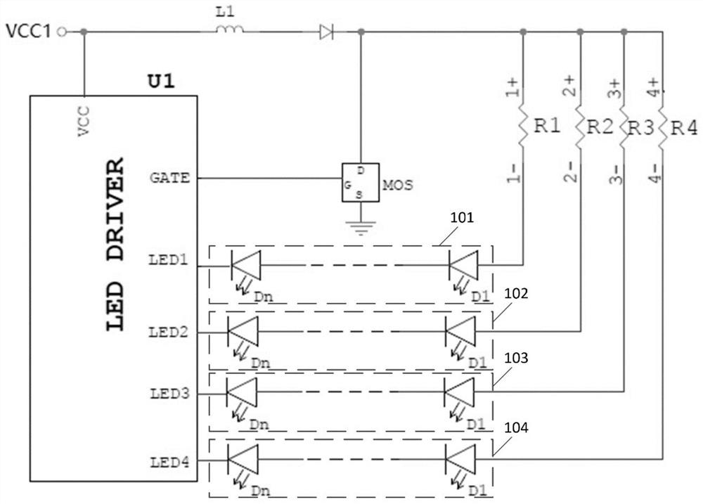
[0070] The driving circuit 200 is used to drive at least one LED module 100 , and the first power supply supplies power to the driving circuit 200 ; the LED detection device 300 is used to detect the working state of the backlight of the at least one LED module 100 . Preferably, as figure 2 As ...

Embodiment 3

[0091] Corresponding to Embodiment 1 or 2, Embodiment 3 of the present invention provides an LED detection method, which is implemented by the LED detection device 300 provided in Embodiment 1 or 2 of the present invention. The flow chart of the method is shown in Figure 4 shown, including the following steps:

[0092] S401, detecting the induced current of at least one sensing resistor 301;

[0093] S402. Determine the backlight working state of the corresponding LED module 100 according to the induced current.

[0094] Preferably, the above step S401 includes: detecting the induced voltage of the sensing resistor 301 , and obtaining the corresponding induced current according to the induced voltage; specifically, the induced current can be calculated from the induced voltage and the known resistance value of the sensing resistor 301 .

[0095] Preferably, the above step S402 includes: converting the induced current into an analog voltage, and determining the corresponding...


PUM


Abstract

Embodiments of the present invention provide an LED detection device, a detection system and a detection method. The detection device is used to detect the working state of the backlight of the LED module. The detection device includes at least one sensing resistor and a detection circuit; at least one of the LED modules is electrically connected to the first end of a corresponding sensing resistor; the detection circuit is electrically connected to each of the sensing resistors; the detection circuit , for detecting the induced current of each sensing resistor, and determining the backlight working state of the corresponding LED module according to the induced current. The embodiments of the present invention can be applied to most LED circuit structures, so as to overcome the limitation of the applicable scope of the existing LED detection devices.

Description

technical field [0001] The invention relates to the technical field of LEDs, in particular, the invention relates to an LED detection device, a detection system and a detection method. Background technique [0002] A liquid crystal display module composed of a liquid crystal screen and a backlight source is increasingly widely used in military and industrial applications. Since the LCD screen itself does not emit light, in order to clearly see the content displayed on the screen, LED (Light Emitting Diode, light-emitting diode) is usually used as the backlight source of the display screen to provide backlight. The normal operation of the LED has a great impact on the function of the LCD module Implementation is critical. [0003] In order to grasp the working status of the LED in time, the existing military LCD modules and industrial LCD modules are required to have the function of monitoring the status of each functional module, especially the LED, so that the working stat...

Claims


Application Information

Patent Timeline
Patent Type & Authority Patents(China)
IPC IPC(8): H05B45/50H05B44/00
CPCH05B45/50
Inventor 刘建福
Owner BOE TECH GRP CO LTD
Why Eureka
Try Eureka