Frequency conversion and constant current control method of LED drive system based on switched capacitor converter

A technology of LED driving and switched capacitors, which is applied in conversion equipment without intermediate conversion to AC, energy-saving control technology, electric light sources, etc., can solve the problem of unstable output voltage, narrow input voltage and output power range, dynamic switching capacitor converter Problems such as slow response time

Active Publication Date: 2020-07-28
XIAN UNIV OF TECH
View PDF3 Cites 0 Cited by
  • Summary
  • Abstract
  • Description
  • Claims
  • Application Information

AI Technical Summary

Problems solved by technology

However, using these traditional control methods, the switched capacitor converter has the disadvantages of slow dynamic response, narrow input voltage and output power range, and unstable output voltage. In addition, these control methods are mainly to realize the constant voltage control method of the switched capacitor converter.
The constant current control method is beneficial to prolong the life of LED lamps and improve the power conversion efficiency. For the constant current control method of the switched capacitor converter, there is no reference in the existing literature and practical applications.

Method used


Image

  • Frequency conversion and constant current control method of LED drive system based on switched capacitor converter
  • Frequency conversion and constant current control method of LED drive system based on switched capacitor converter
  • Frequency conversion and constant current control method of LED drive system based on switched capacitor converter

Examples


Embodiment Construction

[0052] The present invention will be described in detail below with reference to the drawings and specific embodiments.

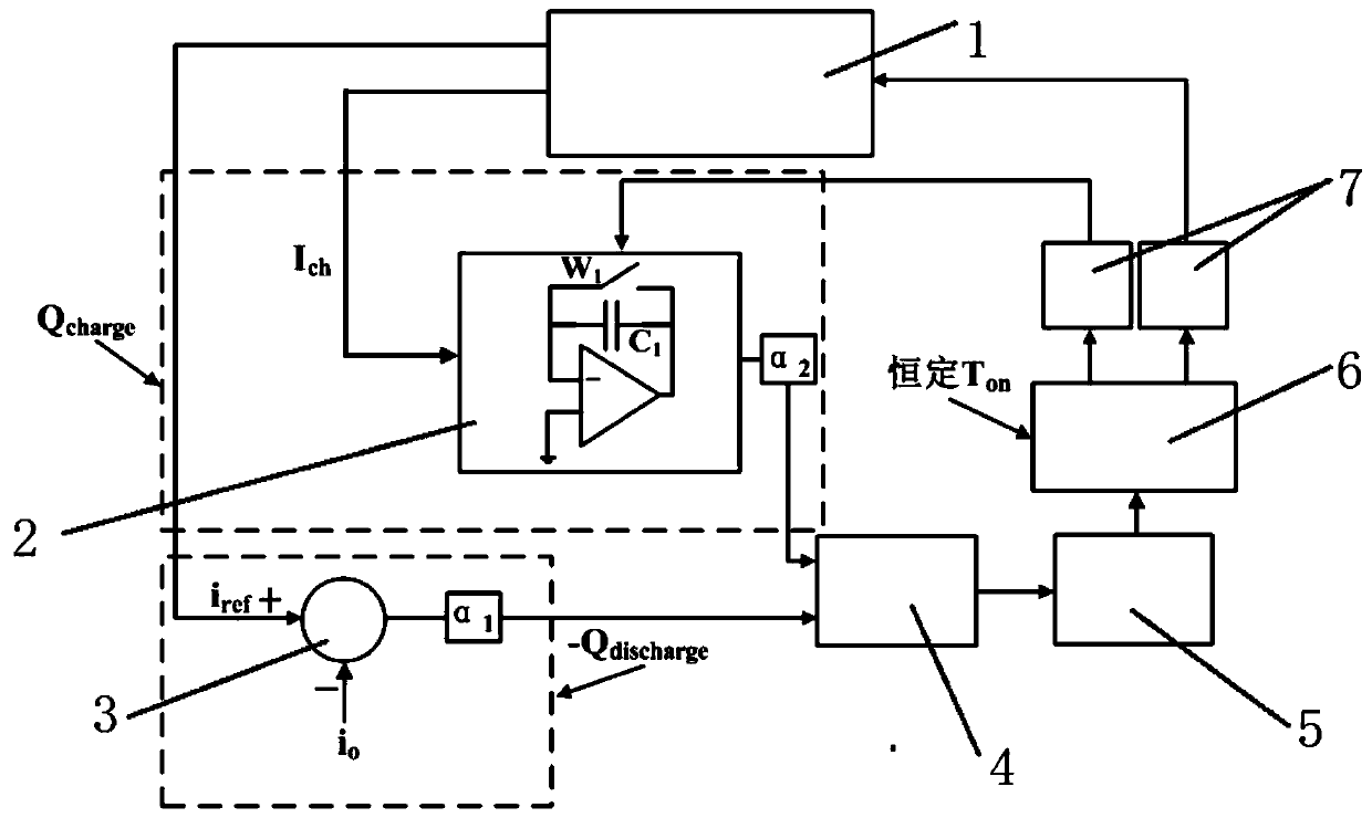
[0053] The present invention is based on the variable frequency constant current control method of the LED drive system of the switched capacitor converter, adopts the variable frequency constant current control system of the LED drive system based on the switched capacitor converter, such as figure 1 As shown, it includes an LED drive system 1 based on a switched capacitor converter. The LED drive system 1 based on a switched capacitor converter is connected with a resettable integrator 2 and an adder-subtractor 3, a resettable integrator 2 and an adder-subtractor 3 The signal output terminals are all connected to the signal input terminal of the comparator 4. The comparator 4 is connected to the D flip-flop 5 and the monostable multivibrator 6 in turn. The output terminals of the monostable multivibrator 6 are connected in parallel with two Output drive sign...


PUM


Abstract

The invention discloses a frequency conversion and constant current control method of an LED drive system based on a switched capacitor converter. The capacitor C in the charging circuit of the LED drive system based on a switched capacitor converter S current I ch As the integral input quantity of , it is sent to the resettable integrator, and the LED drive system based on the switched capacitor converter is given the output current reference quantity I in the discharge circuit ref The overall output current I of the LED drive system based on the switched capacitor converter o Feedback to the adder-subtractor for difference, the output signal of the adder-subtractor and the output signal of the resettable integrator are sent to the comparator for comparison and then sent to the D flip-flop, and then enter the monostable multivibrator, The signal output from the monostable multivibrator is then passed through the output drive signal amplification circuit to drive the switch tube S 1 and switch tube S 2 , so as to achieve the purpose of constant current output, and improve the dynamic response speed of the LED driving system based on the switched capacitor converter.

Description

Technical field [0001] The invention belongs to the technical field of nonlinear control methods, and relates to a variable frequency constant current control method of an LED drive system based on a switched capacitor converter. Background technique [0002] With the more and more widespread application of smart electronic products and the development of other electronic technologies, LEDs have been applied to the lighting field on a certain scale (such as street lighting, home lighting, electric vehicle lighting systems, etc.), and some advanced products require more and more functions The more, so the LED lighting system needs higher performance. Due to the advantages of higher luminous efficiency and longer life, LED has been widely used in domestic or international automation industry, industry and public facilities. The performance of the LED mainly depends on the driver, and its performance will have a very large impact on the LED. With the development of electronic tech...

Claims


Application Information

Patent Timeline
Patent Type & Authority Patents(China)
IPC IPC(8): H05B45/345H02M3/07H02M1/14H05B44/00
CPCH02M1/14H02M3/07H05B45/395H05B45/44H05B45/10Y02B20/30Y02B20/40
Inventor 杨磊于文倩杨曦张嘉翔同向前
Owner XIAN UNIV OF TECH
Why Eureka
Try Eureka