Line dyeing equipment for textile dyeing

A technology for dyeing equipment and textiles, which can be used in the processing of textile material equipment configuration, textile material container processing, spray/jet textile material processing and other directions, which can solve problems such as dye precipitation

Active Publication Date: 2018-08-14
台州佰伴制衣有限公司
View PDF9 Cites 5 Cited by
  • Summary
  • Abstract
  • Description
  • Claims
  • Application Information

AI Technical Summary

Problems solved by technology

[0006] In order to overcome the disadvantages that the dyed lines are not dried and the dyes will precipitate during the dyeing process when dyeing the textile lines, the technical problem to be solved by the present invention is to provide a Thread dyeing equipment for textile dyeing that turns the dye during the drying and dyeing process so that the dye does not settle

Method used


Image

  • Line dyeing equipment for textile dyeing
  • Line dyeing equipment for textile dyeing
  • Line dyeing equipment for textile dyeing

Examples


Embodiment 1

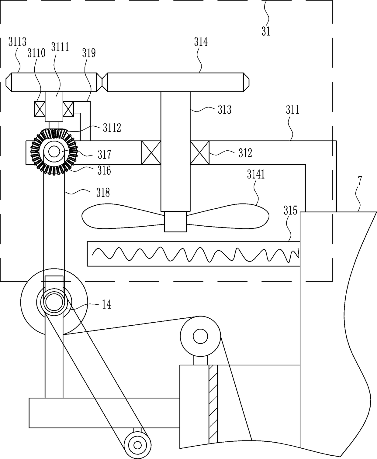
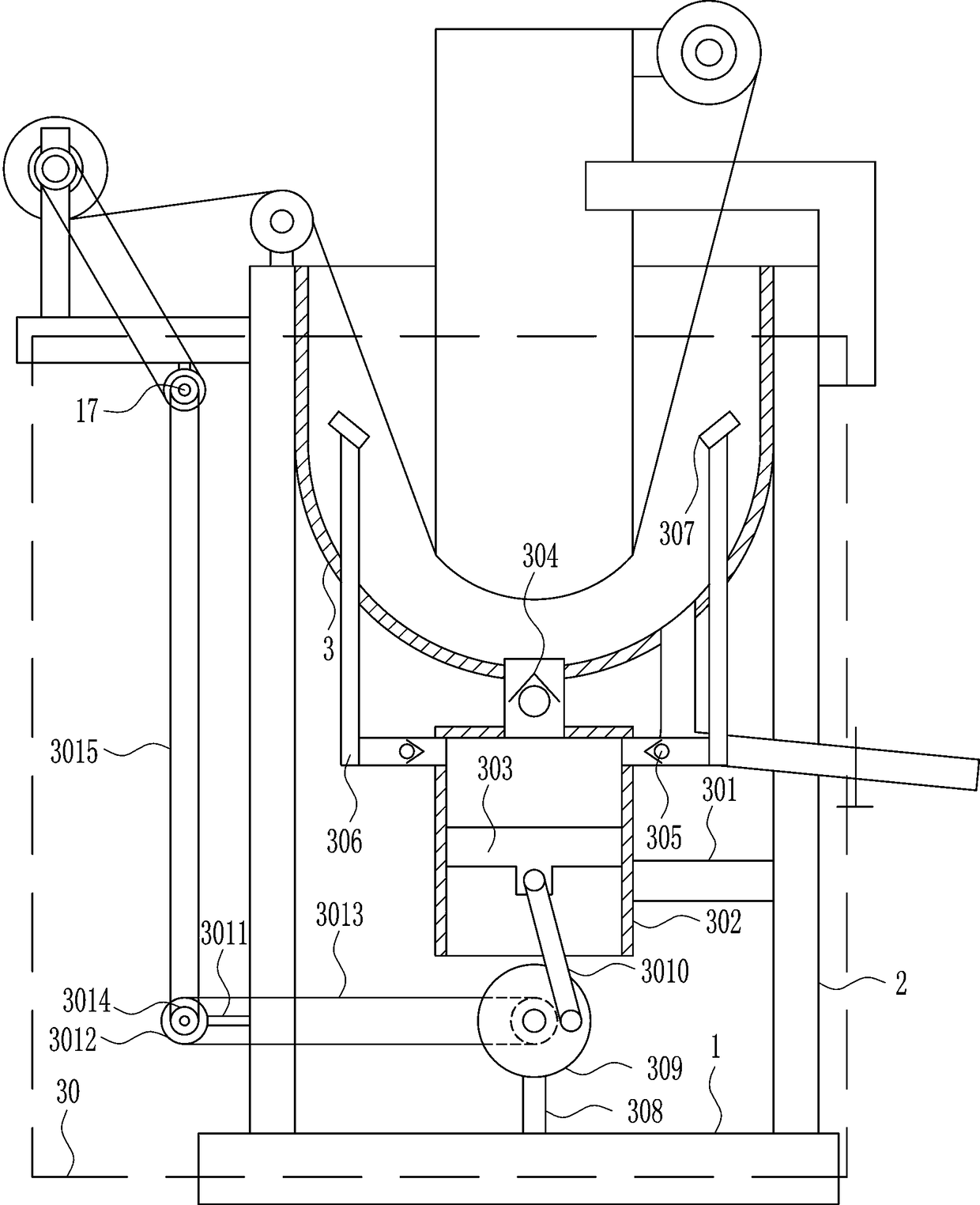
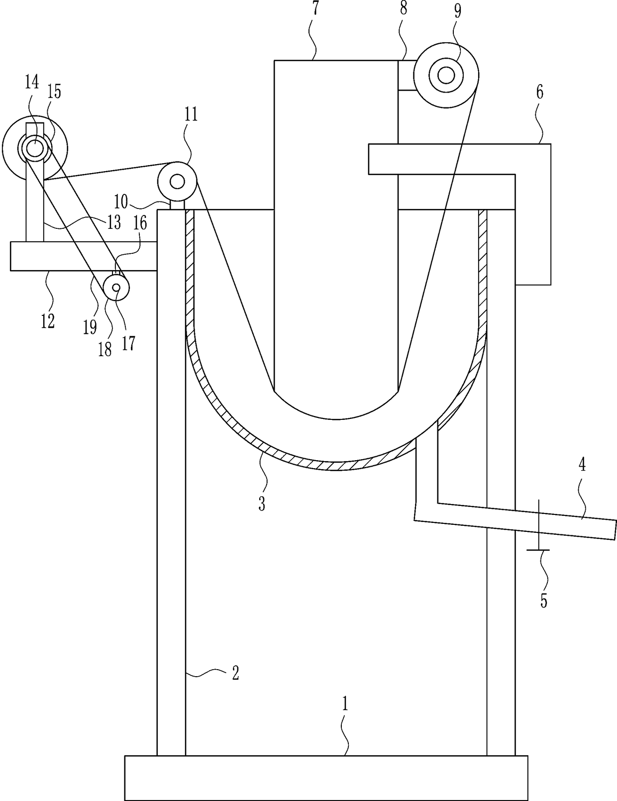
[0028] A kind of line dyeing equipment for textile dyeing, such as Figure 1-5 As shown, it includes a bottom plate 1, a support plate 2, a dye tank 3, a feeding pipe 4, a valve 5, a first L-shaped rod 6, a guide plate 7, a first connecting block 8, a first set of wheels 9, a second connecting Block 10, roller 11, mounting plate 12, first connecting rod 13, rotating shaft 14, second set of wheels 15, third connecting block 16, electric wheel 17, first runner 18 and first transmission bar 19, on the bottom plate 1 The left and right sides are connected with support plate 2, the inner side of the support plate 2 is connected with the dye box 3, the lower side of the dye box 3 is connected with the feeding pipe 4 on the right side, and the feeding pipe 4 is connected with the right side support of the valve 5 The upper right side of the plate 2 is connected with the first L-shaped bar 6, the left side of the first L-shaped bar 6 is connected with the guide plate 7, the upper righ...

Embodiment 2

[0030] A kind of line dyeing equipment for textile dyeing, such as Figure 1-5 As shown, it includes a bottom plate 1, a support plate 2, a dye tank 3, a feeding pipe 4, a valve 5, a first L-shaped rod 6, a guide plate 7, a first connecting block 8, a first set of wheels 9, a second connecting Block 10, roller 11, mounting plate 12, first connecting rod 13, rotating shaft 14, second set of wheels 15, third connecting block 16, electric wheel 17, first runner 18 and first transmission bar 19, on the bottom plate 1 The left and right sides are connected with support plate 2, the inner side of the support plate 2 is connected with the dye box 3, the lower side of the dye box 3 is connected with the feeding pipe 4 on the right side, and the feeding pipe 4 is connected with the right side support of the valve 5 The upper right side of the plate 2 is connected with the first L-shaped bar 6, the left side of the first L-shaped bar 6 is connected with the guide plate 7, the upper righ...

Embodiment 3

[0033] A kind of line dyeing equipment for textile dyeing, such as Figure 1-5 As shown, it includes a bottom plate 1, a support plate 2, a dye tank 3, a feeding pipe 4, a valve 5, a first L-shaped rod 6, a guide plate 7, a first connecting block 8, a first set of wheels 9, a second connecting Block 10, roller 11, mounting plate 12, first connecting rod 13, rotating shaft 14, second set of wheels 15, third connecting block 16, electric wheel 17, first runner 18 and first transmission bar 19, on the bottom plate 1 The left and right sides are connected with support plate 2, the inner side of the support plate 2 is connected with the dye box 3, the lower side of the dye box 3 is connected with the feeding pipe 4 on the right side, and the feeding pipe 4 is connected with the right side support of the valve 5 The upper right side of the plate 2 is connected with the first L-shaped bar 6, the left side of the first L-shaped bar 6 is connected with the guide plate 7, the upper righ...


PUM


Abstract

The invention relates to textile processing equipment, in particular to line dyeing equipment for textile dyeing. The line dyeing equipment for textile dyeing can dry dyed lines, and turns dyestuff ina dying process so that the dyestuff cannot deposit. In order to solve the technical problem, the line dyeing equipment for textile dyeing comprises a bottom plate, supporting plates, a dyestuff box,a discharging tube, a valve, a first L-shaped rod, a guiding plate, a first connecting block, a first sleeve wheel, a second connecting block, a roller and the like; the left side and the right sideof the bottom plate are separately connected with the supporting plates; the dyestuff box is connected between the upper sides of the insides of the supporting plates; and the right of the lower sideof the dyestuff box is connected with the discharging tube. The dyed lines can be dried, and the dyestuff is turned in a dying process and thus cannot deposit.

Description

technical field [0001] The invention relates to a textile processing equipment, in particular to a line dyeing equipment for textile dyeing. Background technique [0002] The original meaning of textile is taken from the general term of spinning and weaving, but with the continuous development and improvement of the textile knowledge system and subject system, especially after the emergence of non-woven textile materials and three-dimensional composite weaving technologies, textile is not only the traditional spinning and weaving Weaving also includes non-woven technology, three-dimensional weaving technology, electrostatic nano-netting technology, etc. [0003] At present, when dyeing textiles, especially when dyeing threads, most of the threads are directly passed through the dye vat, but the disadvantage of this is that if the dyed threads are not dried and then collected , it will cause the lines to stick, and during the dyeing process, some dyes will precipitate, resul...

Claims


Application Information

Patent Timeline
Patent Type & Authority Applications(China)
IPC IPC(8): D06B1/02D06B23/14D06B23/20D06B15/09
CPCD06B1/02D06B15/09D06B23/14D06B23/20
Inventor 邱有萍
Owner 台州佰伴制衣有限公司
Why Eureka
Try Eureka