
Plastic pipe gallery and plastic comprehensive pipe gallery system

A comprehensive pipe gallery and plastic technology, applied in water conservancy projects, artificial islands, underwater structures, etc., can solve the problems of complex process, low production efficiency, long construction period, etc., and achieve simple process, high production efficiency, The effect of low production and construction efficiency

Pending Publication Date: 2018-08-14
冯光淑
View PDF0 Cites 0 Cited by
  • Summary
  • Abstract
  • Description
  • Claims
  • Application Information

AI Technical Summary

Problems solved by technology

[0009] The purpose of the present invention is to solve the problems that the steel or steel-concrete structure pipe gallery used in the prior art has a large weight, and the process of assembling into a comprehensive pipe gallery is complicated, the production efficiency is low, and the construction period is long. A plastic pipe gallery and a plastic integrated pipe gallery system are provided. The pipe gallery is made of high-strength and modified plastics, so that after the pipe gallery is installed in the underground space, it can withstand the pressure load of the surrounding soil and maintain its fixed shape. Since the pipe gallery is made of plastic, material corrosion is avoided, the weight of the pipe gallery is greatly reduced, and the difficulty of transportation and installation is reduced, thereby improving production efficiency. In the integrated pipe gallery, the splicing of the pipe gallery can be realized by means of heating, pressurization or both, without the need to use additional connectors and connecting components, saving materials and improving connection efficiency

Method used


Image

  • Plastic pipe gallery and plastic comprehensive pipe gallery system
  • Plastic pipe gallery and plastic comprehensive pipe gallery system
  • Plastic pipe gallery and plastic comprehensive pipe gallery system

Examples


Embodiment 1

[0077] The plastic pipe gallery of this embodiment is applied to the laying of urban underground engineering pipelines.

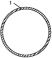
[0078] Plastic pipe gallery, such as figure 1 As shown, it includes a positioning base pipe 1 with a ring-shaped cross-sectional shape. The material of the positioning base pipe 1 is high-strength and its modified and reinforced plastic, and the specific strength of the plastic is greater than 0.1N·m / kg.

[0079] The material of the positioning base pipe 1 in this embodiment adopts high-strength and modified-enhanced plastics. High-strength means that the specific strength of the plastic is greater than 0.1N·m / kg, and the plastic is modified and enhanced, which means adding modified plastics to the plastic. The specific strength of the modified reinforced plastic is also greater than 0.1 N m / kg, so as to ensure that the pipe gallery has high strength and can withstand the surrounding soil when it is applied. The pressure applied will not cause deformation ...

Embodiment 2

[0089] The plastic pipe gallery of this embodiment is applied to the laying of urban underground engineering pipelines.

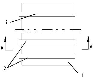
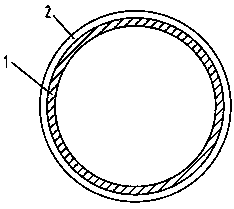
[0090] Plastic pipe gallery, such as figure 2 and image 3As shown, the plastic pipe gallery of this embodiment is basically the same as the plastic pipe gallery of Embodiment 1, the difference is that a plurality of annular reinforcing ribs 2 are arranged on the outer wall of the positioning base pipe 1, and a plurality of said annular reinforcing ribs 2 Arrange along the axial direction of the positioning base pipe 1, and strengthen the positioning base pipe 1 by arranging a ring-shaped reinforcing rib 2 on the outer wall of the positioning base pipe 1, so that the positioning base pipe 1 has a higher strength in the length direction , and, after arranging the annular reinforcing rib 2, when the plastic pipe gallery is installed in an underground tunnel, the annular reinforcing rib 2 can increase the frictional resistance between the pipe gallery and th...

Embodiment 3

[0093] Plastic pipe gallery, such as Figure 4 As shown, it includes a positioning base pipe 1 with a ring-shaped cross-sectional shape. The material of the positioning base pipe 1 is high-strength and its modified and reinforced plastic, and the specific strength of the plastic is greater than 0.1N·m / kg.

[0094] The outer wall of the positioning base pipe 1 in this embodiment is also sleeved with an outer wall pipe 3. The cross-sectional shape of the outer wall pipe 3 corresponds to the cross-sectional shape of the positioning base pipe 1. The cross-sections of the positioning base pipe 1 and the outer wall pipe 3 in this embodiment The shapes are all ring-shaped, and connecting ribs 4 are connected between the outer wall pipe 3 and the positioning base pipe 1 .

[0095] According to the technical solution of this embodiment, it is easy to think that the connecting ribs 4 can be arranged horizontally or vertically, so that the connecting ribs can only include horizontal conn...


PUM

PropertyMeasurementUnit
Strengthaaaaaaaaaa

Abstract

The invention relates to urban underground pipeline facilities, in particular to a plastic pipe gallery and a plastic comprehensive pipe gallery system. The plastic pipe gallery comprises a positioning base pipe, wherein the cross section of the positioning base pipe is generally circular or rectangular, the positioning base pipe is made of high-strength and modified reinforced plastic, and the specific strength of the plastic is larger than 0.1 N.m / kg. The pipe gallery adopts the high-strength and modified reinforced plastic, and therefore the pressure load of a surrounding soil body can be borne and the fixed shape of the pipe gallery can be kept after the pipe gallery is installed in the underground space; due to the fact that the pipe gallery adopts plastic, anti-corrosion measures arenot needed to be carried out on the pipe gallery, the weight of the pipe gallery is greatly reduced, and the transportation and installation difficulty is lowered, so that the production efficiency and the construction efficiency are improved; and in addition, the pipe gallery made of plastic is adopted, when the comprehensive pipe gallery system is formed by splicing the plurality of pipe galleries, the pipe galleries can be spliced in a mode of heating, a mode of pressurization or a mode of heating and pressurization, extra connecting pieces and connecting components are not needed, so thatmaterials are saved, and the connecting efficiency is improved.

Description

technical field [0001] The invention relates to urban underground pipeline facilities, in particular to a plastic pipe gallery and a plastic comprehensive pipe gallery system. Background technique [0002] The comprehensive pipe gallery is a comprehensive corridor of underground urban pipelines and cables. By building a tunnel space underground in the city, and then installing the pipe gallery, various engineering pipelines such as power, communication, gas, heating, water supply and drainage are integrated and arranged in one In the pipe gallery, the comprehensive pipe gallery is equipped with special inspection ports, hoisting ports and monitoring systems. It implements unified planning, design, construction and management, and is an important infrastructure and lifeline to ensure the operation of the city. The integrated pipe gallery system not only solves the problem of urban traffic congestion, but also greatly facilitates the maintenance and repair of municipal facilit...

Claims


Application Information

Patent Timeline
IPC IPC(8): E02D29/045
CPCE02D29/045
Inventor 冯光淑
Owner 冯光淑
Learn More