
Scrap steel preheating system

A technology for scrap steel and kiln, applied in the direction of preheating fee, lighting and heating equipment, furnace, etc., can solve the problems of reducing the utilization rate of heat energy, low preheating efficiency, water leakage, etc., to save the cooling problem and shorten the preheating cycle , to meet the effect of preheating requirements

Pending Publication Date: 2018-08-14
上海轩鼎冶金科技集团有限公司
View PDF0 Cites 1 Cited by
  • Summary
  • Abstract
  • Description
  • Claims
  • Application Information

AI Technical Summary

Problems solved by technology

After preheating, the container needs to be hoisted out before the next round of preheating. During this period, the interval is long and the heat loss is large, so the preheating efficiency is low.
[0007] (2) The container is heated for a long time, which is prone to deformation and rupture. Some sites weld the water cooling system outside the container. However, the weld seam is easy to open due to heat, causing water leakage problems, and the working environment of constant alternating cold and heat has a negative impact on the container and the water cooling system itself. The processing technology puts forward higher requirements
[0008] (3) The scrap steel is preheated through the container, and the heating is uneven, so the preheating efficiency is low; at the same time, the container absorbs heat, which reduces the utilization rate of heat energy
[0009] (4) The kiln used for preheating usually adopts a steel structure outer frame with built-in fibers, refractory bricks, and castables. The heated container is placed on the water beam in the furnace, and the container and the scrap steel contained in it are uniform There is no direct contact with the furnace wall and furnace bottom, so it is difficult to meet the preheating requirements

Method used


Image

  • Scrap steel preheating system
  • Scrap steel preheating system
  • Scrap steel preheating system

Examples


Embodiment Construction

[0038] The following will be described in detail in conjunction with the accompanying drawings and specific embodiments.

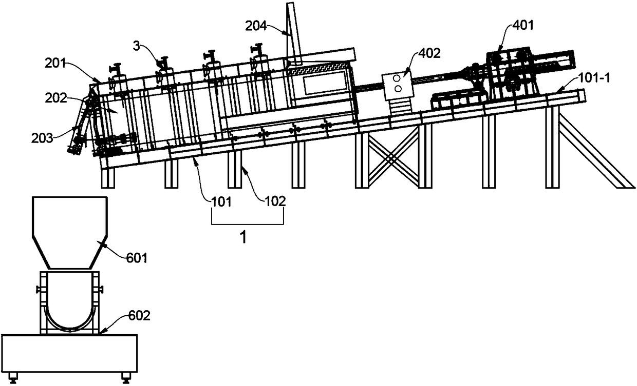
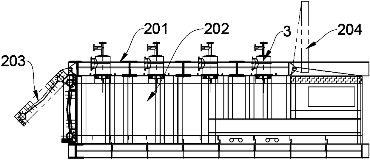
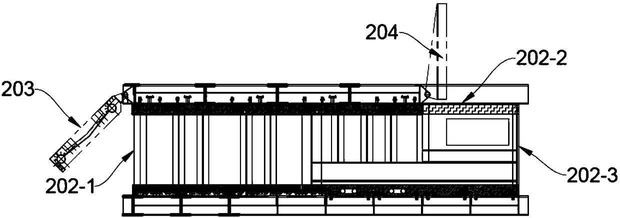
[0039] Such as figure 1 As shown, a steel scrap preheating system includes a kiln 2 , a conveying device, an installation frame 1 , a steel pushing mechanism 4 and a burner 3 . Among them, the kiln 2 is fixed on the mounting frame 1 by fasteners, and the burner 3 is installed on the kiln 2 for preheating scrap steel; the left end of the kiln 2 is a discharge port that can be opened and closed, and the right end is a The opening and closing of the steel pushing port is controlled by the steel pushing mechanism 4, and the side of the kiln 2 is provided with a feed port that can be opened and closed; the conveying device is used to put scrap steel into the kiln 2 from the feed port; The steel mechanism 4 is fixed on the mounting frame 1 and performs a reciprocating linear motion for pushing the preheated steel scrap out of the kiln 2 .

[0040] When scrap s...


PUM


Abstract

The invention relates to a scrap steel preheating system. The scrap steel preheating system comprises a kiln, a conveying device, a mounting bracket, a steel pushing mechanism and a burner. The kiln is fixed on the mounting frame through fasteners, and the burner is installed on the kiln and used for preheating scrap steel. The left end of the kiln is an openable and closable discharging port, theright end of the kiln is a steel pushing port, the opening and closing of the steel pushing port is controlled by the steel pushing mechanism, and an openable and closable feeding port is formed in the side surface of the kiln. The conveying device is used for putting the scrap steel into the kiln from the feeding port. The steel pushing mechanism is fixed on the mounting bracket, does reciprocating linear motion and is used for pushing the preheated scrap steel out of the kiln. According to the scrap steel preheating system, the scrap steel is directly preheated by the kiln, the preheated scrap steel is pushed out by a steel pushing machine, the time in taking out the scrap steel from the kiln is shortened greatly by the adoption of the steel pushing machine, the time is counted in seconds, and thus continuous preheating of the scrap steel is realized.

Description

technical field [0001] The invention relates to a system for preheating scrap steel, in particular to a continuous scrap steel preheating system. Background technique [0002] According to data from the World Steel Association, global steel production in 2017 was 1.6912 billion tons, a year-on-year increase of 5.3%. Asia’s annual crude steel production reached 1.1625 billion tons, a year-on-year increase of 5.4%. India’s crude steel production was 101.4 million tons, a year-on-year increase of 6.2%. , South Korea's crude steel production was 71.1 million tons, a year-on-year increase of 3.7%; the total crude steel production in the EU region (28 countries) was 168.7 million tons, a year-on-year increase of 4.1%; the total crude steel production in North America in 2017 was 116 million tons tons, a year-on-year increase of 4.8%. The World Steel Association predicts that global steel demand will increase again by 1.6% to 1.72 billion tons in 2018, and global steel demand will...

Claims


Application Information

Patent Timeline
Patent Type & Authority Applications(China)
IPC IPC(8): F27D13/00
CPCF27D13/002
Inventor 赵猛张振锋
Owner 上海轩鼎冶金科技集团有限公司
Learn More