Telescopic multimeter pen head

A multimeter and telescopic technology, which is applied in the direction of instruments, measuring devices, measuring electricity, etc., can solve the problems of unsafe operation of equipment, short relative distance between terminals, electric shock of testing personnel, etc., to achieve free control of position and distance, and strengthen reliability performance, accuracy, and increased detection range

Active Publication Date: 2018-08-14
STATE GRID CORP OF CHINA +1
View PDF6 Cites 1 Cited by
  • Summary
  • Abstract
  • Description
  • Claims
  • Application Information

AI Technical Summary

Problems solved by technology

[0002] In recent years, with the increasing number of newly built substations, the daily workload has also gradually increased. In some tasks, it is necessary to use a multimeter for measurement work, such as regular measurement of battery voltage and other substation daily maintenance work. Due to the existing multimeter pen contact Short, the distance between the terminals that need to be measured is not enough in the actual measurement work, and the problem of equipment installation will also cause some terminals to be relatively close to the inside of the equipment, and the terminals cannot be reached during the measurement. Forced measurement may cause people to touch the terminals by mistake, causing equipment Major safety accidents such as short circuit, tripping, and electric shock to testing personnel
[0003] In the past work, due to the short contact of the multimeter pen, the method of adding wires is generally used for measurement. This method is to directly wind the wires on the contacts of the multimeter. Since the wires are relatively soft and easy to bend, the terminals between the terminal blocks are compared. The dense relative distance is very short, and it is very easy to accidentally touch other terminals and wires, which not only makes the measurement inconvenient, but also brings unsafe factors to the safe operation of the equipment

Method used


Image

  • Telescopic multimeter pen head
  • Telescopic multimeter pen head
  • Telescopic multimeter pen head

Examples


Embodiment Construction

[0034] Combine below Figure 1-5 To further describe the present invention.

[0035] The present invention adopts following technical scheme:

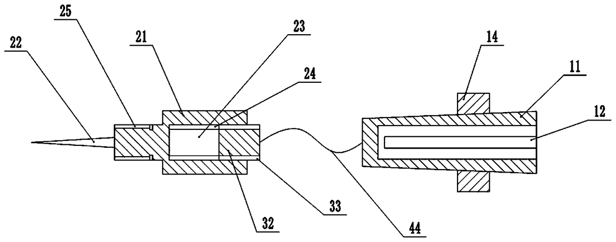
[0036] A retractable multimeter lead, including a connection part, a detection head and a connection line;

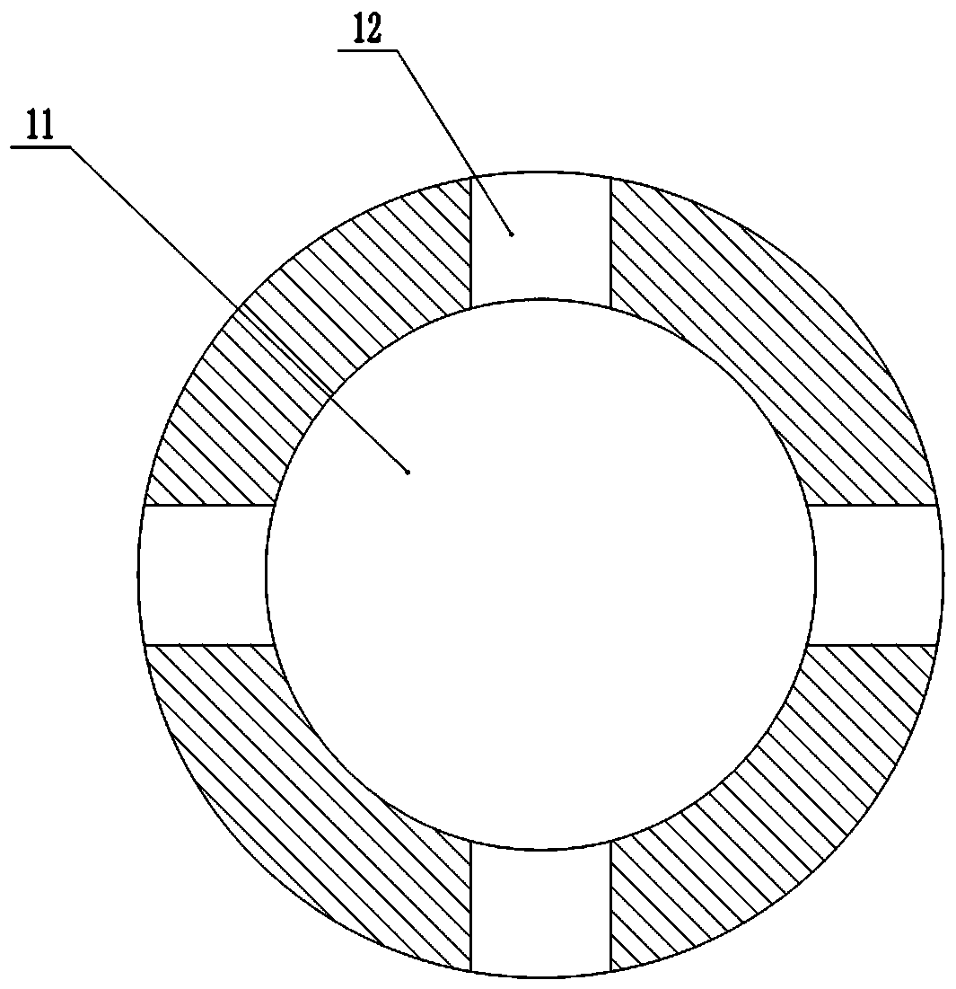
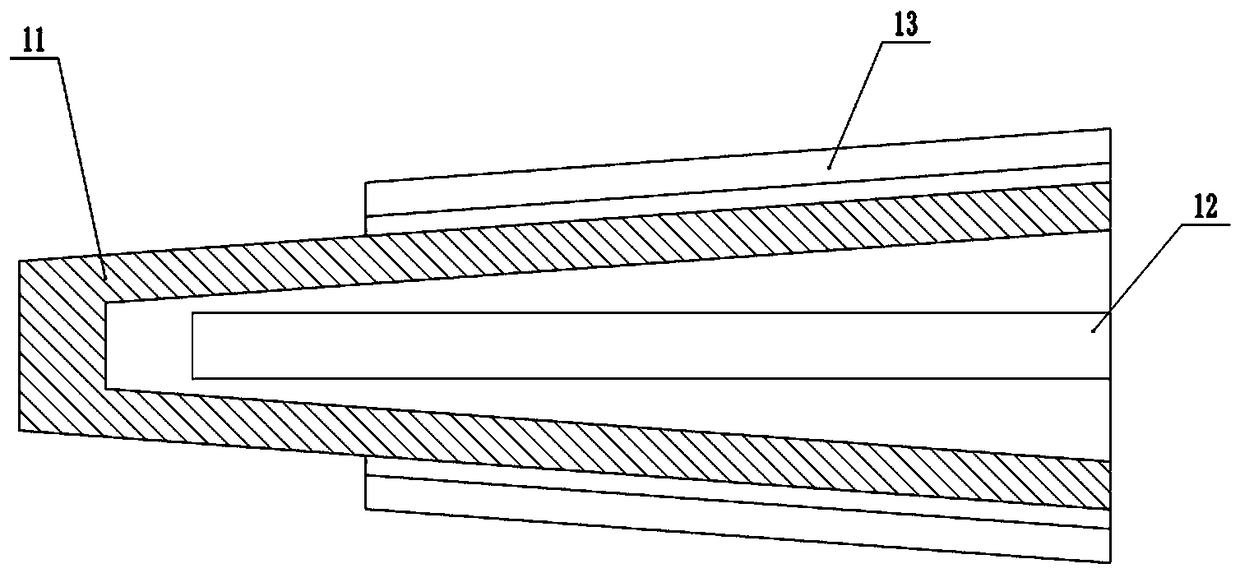
[0037] The connecting part comprises a connecting pipe 11, long grooves 12 evenly distributed on the outer wall of the connecting pipe 11, threads 13 arranged on the outer wall of the connecting pipe 11 and fastening nuts 14 threadedly connected with the connecting pipe 11;

[0038] One end of the long groove 12 is an open end, and the other end is a closed end;

[0039] One end of the connecting pipe 11 is a closed end, and the other end is an open end;

[0040] The detection head includes a detection cylinder 21, a probe 22 fixed at one end of the detection cylinder 21, a hole 23 at the other end of the detection cylinder 21, a connecting thread A24 on the inner wall of the hole 23 and a screw thread on the outer wall of th...


PUM


Abstract

The invention discloses a telescopic multimeter pen head. The telescopic multimeter pen head comprises a connecting part, a detection head and a connecting line; the connecting part comprises a connecting pipe, long grooves uniformly distributed on the outer wall of the connecting pipe, a thread which is arranged on the outer wall of the connecting pipe and a fastening nut connected with the thread of the connecting pipe; the detection head comprises a detection cylinder, a probe fixed to one end of the detection cylinder, a hole which is formed in the other end of the detection cylinder, a connecting thread A which is arranged on the inner wall of the hole and a connecting thread B which is arranged on the outer wall of the detection cylinder; the connecting line comprises a wire, a connecting head fixed to one end of the wire, a connecting thread C arranged on the outer wall of the connecting head and a protecting layer; the protecting layer comprises a first insulating layer covering the wire, a stainless steel wire net covering the first insulating layer, a second insulating layer covering the stainless steel wire net and an outer protecting layer covering the second insulatinglayer.

Description

technical field [0001] The invention relates to the field of electric power detection tools, in particular to a retractable multimeter tip. Background technique [0002] In recent years, with the increasing number of newly built substations, the daily workload has also gradually increased. In some tasks, it is necessary to use a multimeter for measurement work, such as regular measurement of battery voltage and other substation daily maintenance work. Due to the existing multimeter pen contact Short, the distance between the terminals that need to be measured is not enough in the actual measurement work, and the problem of equipment installation will also cause some terminals to be relatively close to the inside of the equipment, and the terminals cannot be reached during the measurement. Forced measurement may cause people to touch the terminals by mistake, causing equipment Major safety accidents such as short circuit, tripping, and electric shock to testing personnel. ...

Claims


Application Information

Patent Timeline
Patent Type & Authority Applications(China)
IPC IPC(8): G01R15/12G01R1/067
CPCG01R1/06788G01R15/12
Inventor 李勇郭广森宋桂贤
Owner STATE GRID CORP OF CHINA
Why Eureka
Try Eureka