Crusher

A pulverizer and casing technology, which is applied in the field of electromechanical devices, can solve the problems of low heat dissipation effect and high noise, and achieve the effect of low noise, broad prospects and high heat dissipation effect

Inactive Publication Date: 2018-08-17
SUQIAN GENERAL MACHINERY
View PDF0 Cites 2 Cited by
  • Summary
  • Abstract
  • Description
  • Claims
  • Application Information

AI Technical Summary

Problems solved by technology

At present, the pulverizer has the proble

Method used


Image

  • Crusher
  • Crusher
  • Crusher

Examples


specific Embodiment approach

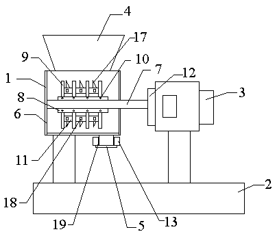
[0016] figure 1 Show the specific embodiment of the present invention: a kind of pulverizer, comprise casing 1, base 2, motor 3 and crushing structure, described casing 1 and motor 3 are arranged on the base 2, the upper and lower ends of described casing 1 A feed port 4 and a discharge port 5 are provided, a wear-resistant liner 6 is provided on the inner wall of the casing 1, and the crushing structure includes a main shaft 7, a hammer frame 8 and a hammer 9, and the hammer frame 8 are set on the upper and lower sides of the main shaft 7, the hammer 9 is set on the hammer frame 8 through screws 10, spacers 11 are arranged between the hammers 9, and the motor 3 and the main shaft 7 are connected through a coupling 12, and vibration motors 13 are arranged on both sides of the discharge port 5.

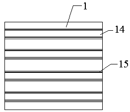
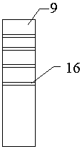
[0017] In addition, if figure 2 and 3 As shown, the outer wall of the casing 1 is provided with a heat dissipation groove 14, the heat dissipation groove 14 is provided with a heat...


PUM


Abstract

The invention discloses a crusher. A radiating groove is formed in the outer wall of a shell, a radiating film is arranged in the radiating groove, radiating efficiency can be improved by matching theradiating groove with the radiating film, bumps are arranged on a hammer, the service time of the hammer can be prolonged, and an anti-winding piece is arranged on a separator and can solve the problem of motor burnout caused by winding. A rubber pad is arranged between a discharging port and a vibrating motor, noise can be reduced in vibration, noise pollution is reduced, and the crusher has theadvantages of high radiating effects and low noise and is wide in prospect.

Description

technical field [0001] The invention relates to the field of electromechanical devices, in particular to a pulverizer. Background technique [0002] A pulverizer is a machine that crushes large-sized solid raw materials into required sizes. The pulverizer is composed of coarse crushing, fine crushing, wind conveying and other devices, and achieves the purpose of pulverizing in the form of high-speed impact. The working principle of the pulverizer is: after the material enters the crushing chamber, it is crushed by the impact of the high-speed rotary hammer and further crushed after friction and collision. The material particles that meet the particle size requirements are discharged from the discharge port through the sieve under the action of centrifugal force and gravity. At present, the pulverizer has the problems of low heat dissipation effect and high noise. Contents of the invention [0003] The technical problem to be solved by the present invention is to provide ...

Claims


Application Information

Patent Timeline
IPC IPC(8): B02C13/06B02C13/26B02C13/28B02C18/14
CPCB02C13/06B02C13/26B02C13/28B02C18/145
Inventor 杜爱民崔伯第郜志强陈茂辉
Owner SUQIAN GENERAL MACHINERY
Why Eureka
Try Eureka