Laser cutting machine of board or strip

A laser cutting machine and strip technology, applied in the direction of laser welding equipment, welding/cutting auxiliary equipment, auxiliary devices, etc., can solve the problems of limiting the cutting accuracy and inaccuracy of laser cutting machines, and achieve the effect of controlling inertia

Pending Publication Date: 2018-08-17
金凯达(佛山)智能装备有限公司
View PDF1 Cites 4 Cited by
  • Summary
  • Abstract
  • Description
  • Claims
  • Application Information

AI Technical Summary

Problems solved by technology

[0004] However, this structure has a very big disadvantage: since the laser head is driven by the horizontal drive mechanism and the longitudinal drive, each movement will generate inertia. In fact, each inertia may cause inaccurate cutting of the machine, so This limits the cutting accuracy of the laser cutting machine

Method used


Image

  • Laser cutting machine of board or strip
  • Laser cutting machine of board or strip
  • Laser cutting machine of board or strip

Examples


Embodiment 1

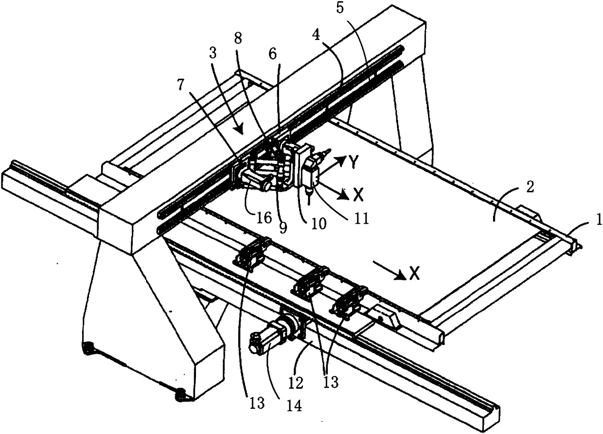
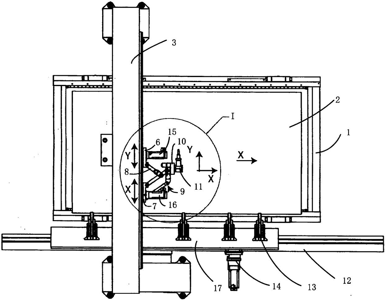
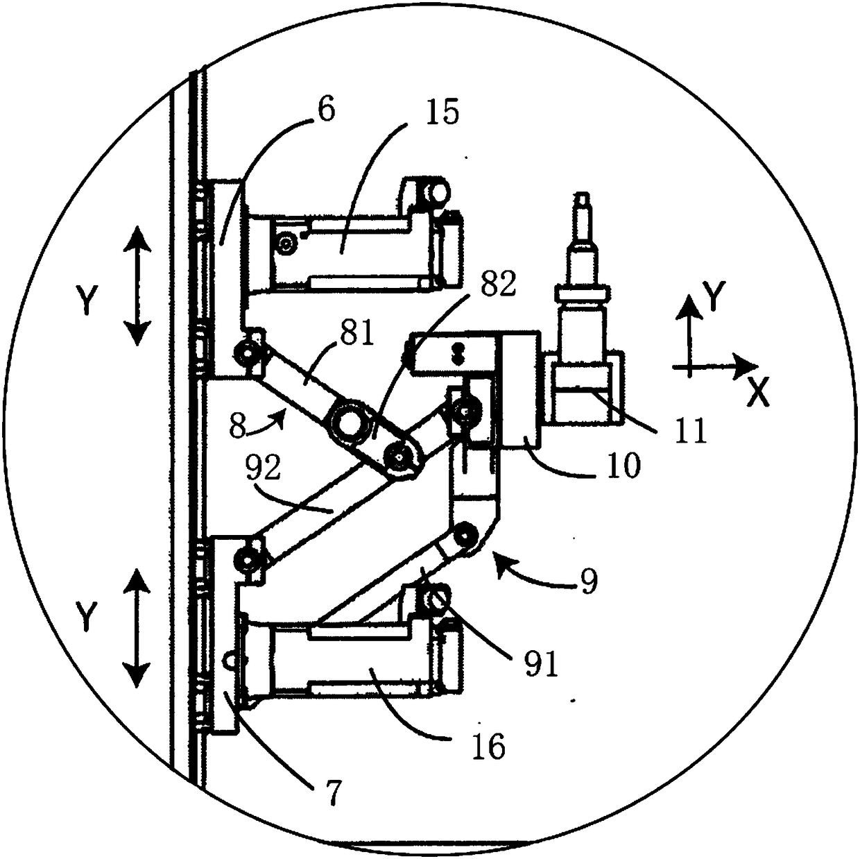
[0026] like figure 1 , 2 , 3, a laser cutting machine for a plate 2 or a strip, including a worktable 1 and a laser head 11, the laser cutting machine in this embodiment is used to cut discrete plates 2 or strips, the laser cutting machine also It includes a gantry 3 across the top of the worktable 1. The gantry 3 has a transversely extending beam on which a transverse guide rail 4 is arranged. The plate 2 or strip can be pulled on the worktable 1 to move horizontally and vertically. , in this embodiment, side supports 12 are provided on the side of the worktop 1, and longitudinal guide rails are provided on the side supports 12, and a longitudinal moving plate 17 is installed longitudinally on the longitudinal guide rails, and the longitudinal moving plate 17 is fixed There are several traction fixtures 13 for clamping the plate 2 or the edge of the strip. In the present embodiment, the traction fixtures 13 are four sets. Just hold the edge of the plate 2. The longitudinal...

Embodiment 2

[0035] like Figure 4 As shown, the structure in this embodiment is the same as the structure in Embodiment 1, except that the sheet 2 or strip cut in this embodiment is a coil, such as Figure 4 As shown, the coil is placed on the unwinder and pulled horizontally by the tractor to move the sheet 2 or strip longitudinally over the work surface 1 . Both the unwinder and the tractor are the current conventional technologies, and the tractor can be driven by a servo motor to precisely control the unwinding speed of the coil.

[0036] The actuators such as cylinders, servo motors, and rack-and-pinion mechanisms mentioned in this embodiment are all current conventional technologies. The specific structure and principle and other designs of the cylinder, motor and other transmission mechanisms are disclosed in detail in the book, which belongs to the prior art, and its structure is clear and clear. The Modern Practical Pneumatic Technology No. 1 published by the Machinery Industry ...


PUM


Abstract

The invention discloses a laser cutting machine of a board or a strip. The laser cutting machine of the board or the strip comprises a working table surface, a laser head and a portal frame crossing the upper part of the work table surface, and the board or the strip can be pulled to move horizontally and vertically on the working table surface. The portal frame is slidably and horizontally provided with a first sliding block and a second sliding block in the transverse direction, the laser head is installed on an installation seat and is arranged downwards, and a first connecting rod mechanism is connected between a first sliding seat and the installation seat in a hinged mode. A second connecting rod mechanism is connected between a second sliding seat and the installation seat or between the second sliding seat and the first connecting rod mechanism, and the first sliding block and the second sliding block are separately driven by a first transverse power device and a second transverse power device to move independently, so that the laser head can move in the transverse direction or in the longitudinal direction or in the resultant movement direction of the first sliding block and the second sliding block. The laser cutting machine of the board or the strip can reduce inertia and improves cutting accuracy.

Description

technical field [0001] The invention relates to a laser cutting machine, especially for cutting plates or strips. Background technique [0002] The laser cutting machine uses the laser emitted by the laser head to focus into a high-power-density laser beam through the optical path system. The laser beam irradiates the surface of the workpiece to make the workpiece reach the melting point or boiling point, and at the same time, the high-pressure gas coaxial with the beam blows away the molten or vaporized metal. With the movement of the relative position of the beam and the workpiece, the material will eventually form a slit, so as to achieve the purpose of cutting. [0003] The most commonly used sheet metal laser cutting machine is a laser cutting machine equipped with a moving cutting device and a non-moving working part (that is, a metal sheet). For example, a laser cutting machine (Patent No. CN201020112276.6) discloses a laser cutting machine whose laser head can move...

Claims


Application Information

Patent Timeline
Patent Type & Authority Applications(China)
IPC IPC(8): B23K26/38B23K26/08B23K26/70B23K37/04
CPCB23K26/38B23K26/083B23K26/0876B23K26/702B23K37/0408
Inventor 柯晓华
Owner 金凯达(佛山)智能装备有限公司
Why Eureka
Try Eureka