Welding automatic clamp used for stirring friction welding and control method thereof

A friction stir welding and automatic technology, applied in welding equipment, welding equipment, auxiliary welding equipment, etc., can solve the problems of poor work efficiency, low degree of automation, high labor cost, etc., to achieve improved versatility, high degree of automation, and reduced labor cost effect

Active Publication Date: 2018-08-17
宁波友智机械科技有限公司
View PDF8 Cites 5 Cited by
  • Summary
  • Abstract
  • Description
  • Claims
  • Application Information

AI Technical Summary

Problems solved by technology

[0003] In the process of friction stir welding, in order to prevent the workpiece to be welded from shifting and ensure the welding effect, welding fixtures must be used to fix the workpiece to be welded. However, in the current prior art, the welding fixture of friction stir welding generally uses manual quick clamps To fix the workpiece to be welded, when the fixed part needs to be welded, it is necessary to manually open the manual quick clamp, which has poor work efficiency, low degree of automation, and high labor costs

Method used


Image

  • Welding automatic clamp used for stirring friction welding and control method thereof
  • Welding automatic clamp used for stirring friction welding and control method thereof
  • Welding automatic clamp used for stirring friction welding and control method thereof

Examples


Embodiment 1

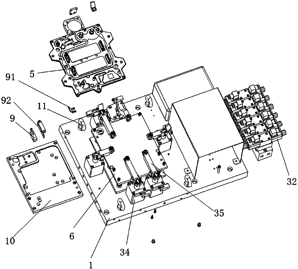
[0041] see Figure 1 to Figure 5 As shown, it is an exploded view of the welding automatic fixture used for friction stir welding of the present invention, a structural schematic diagram of the hydraulic mechanism, a perspective view, a perspective view of the hydraulic cylinder and a perspective view of the bracket.

[0042] combine figure 1 with figure 2 As shown, a welding automatic fixture for friction stir welding includes a base plate 1, a controller 2, a hydraulic mechanism 3, a detection device 4 and a bracket 6 for placing workpieces 5 to be welded. The holes are used to fix the bracket 6 on the bottom plate 1 by screws, and the hydraulic mechanism 3 and the detection device 4 are both connected to the controller 2 .

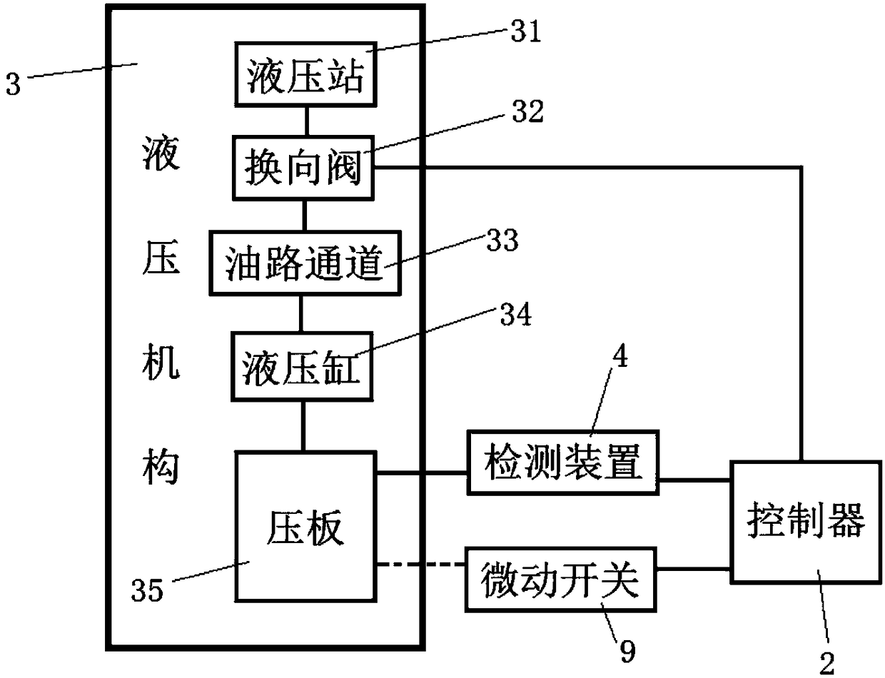
[0043] Such as figure 2 As shown, the hydraulic mechanism 3 includes a hydraulic station 31, a reversing valve 32, an oil channel 33, and a hydraulic cylinder 34 connected in sequence, and the hydraulic cylinder 34 is provided with a pressing plate...

Embodiment 2

[0059] The difference between the above-mentioned automatic welding fixture for friction stir welding in this embodiment is that the reversing valve 32 is connected to the hydraulic cylinder 34 in a one-to-one correspondence, and the hydraulic cylinder 34 is connected to the reversing valve 32 Connected by the oil channel 33, iron filings or powder will be produced on the surface of the workpiece when the workpiece is processed. If the oil channel 33 is arranged on the outer surface, iron filings or powder are likely to accumulate on the oil channel, and it is difficult to clean. In this embodiment, the oil channel 33 is arranged in the base plate 1, and the material of the base plate 1 is generally a stainless steel plate. The wiring design of the oil channel 33 is carried out inside the base plate 1 through a special process, so that the hydraulic cylinder 34 and Oil supply can work normally between reversing valve 32.

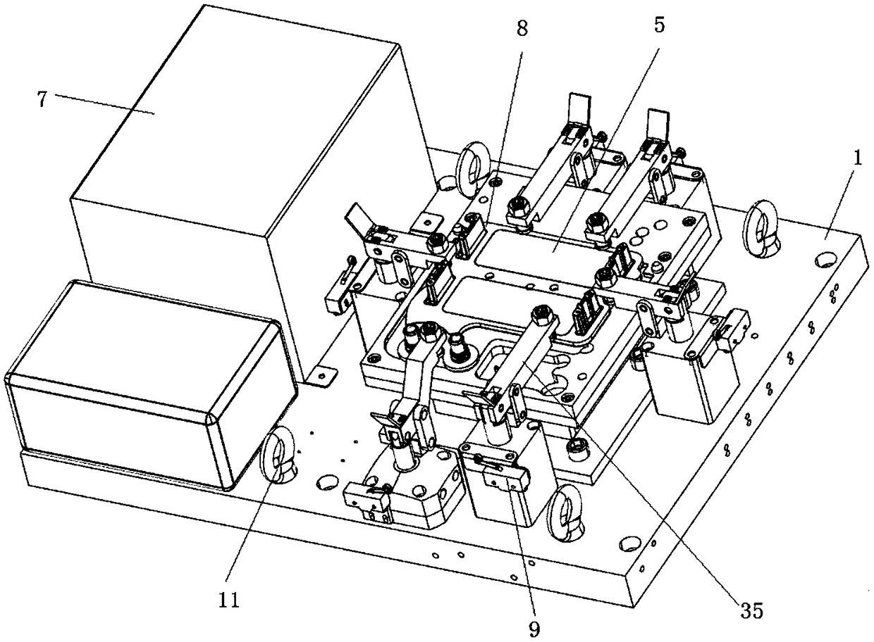
[0060] In this example, if Figure 6 to Figure 11 sho...

Embodiment 3

[0063] As described above, a welding automatic fixture for friction stir welding, the difference between this embodiment and the first embodiment is that, as Figure 4 As shown, the hydraulic cylinder 34 is provided with a micro switch 9, and the pressing plate 35 is provided with a micro switch pressing block 91, and the position of the micro switch 9 is adapted to the position of the micro switch pressing block 91, When the pressing plate 35 releases the workpiece and is in a lifted state, the microswitch pressing block 91 touches the switch of the microswitch 9 . The micro switch 9 is fixed on the hydraulic cylinder 34 through a micro switch bracket 92 provided on the hydraulic cylinder 34 .

[0064] The micro switch 9 is a contact mechanism with a small contact interval and a snap action mechanism, which performs switching action with a predetermined stroke and a predetermined force. It is covered with a shell, and an operating reed is provided outside it. When the micros...


PUM


Abstract

The invention firstly provides a welding automatic clamp used for stirring friction welding. The welding automatic clamp comprises a bottom plate, a controller, a hydraulic mechanism, a detection device and a support used for placing a to-be-welded workpiece; assembly holes is formed in the support and are used for fixing the support on the bottom plate through screws; the hydraulic mechanism andthe detection device are both connected with the controller; and secondly, the invention provides a control method of the welding automatic clamp used for stirring friction welding. The welding automatic clamp used for stirring friction welding has the advantages that the to-be-welded workpiece is limited by adopting the hydraulic mechanism; the automation degree is high; and labor cost is greatlylowered.

Description

technical field [0001] The invention relates to the technical field of friction stir welding, in particular to an automatic welding fixture for friction stir welding and a control method thereof. Background technique [0002] Friction stir welding is a method of using the heat generated by the mutual movement and friction of the end faces of the workpieces to make the ends reach a thermoplastic state, and then quickly upset to complete the welding. Friction stir welding can easily join the same or dissimilar materials, including metals, some metal matrix composites, ceramics and plastics. The friction welding method has been used in the manufacturing industry for more than 40 years. Due to its high productivity and good quality, it has been widely used in engineering applications, such as in aerospace, rail transit, national defense, ships and automobiles. In the process of friction stir welding, a stirring head is used to insert the part to be welded of the workpiece, and ...

Claims


Application Information

Patent Timeline
Patent Type & Authority Applications(China)
IPC IPC(8): B23K37/04B23K20/26B23K20/12
CPCB23K20/126
Inventor 王西海闫同刚
Owner 宁波友智机械科技有限公司
Why Eureka
Try Eureka