A bottom device for a cement silo

A technology of cement storage and control circuit, applied in cement mixing device, control device, clay preparation device, etc., can solve the problems of increasing cement unit cost, reducing cement agglomeration effect, and high power consumption of Roots blower, so as to strengthen the prevention and control. Hardening effect, reduction of cement unit cost, reduction of social disputes

Active Publication Date: 2019-11-01
BINZHOU POLYTECHNIC
View PDF2 Cites 0 Cited by
  • Summary
  • Abstract
  • Description
  • Claims
  • Application Information

AI Technical Summary

Problems solved by technology

[0005] ② Long storage time: the longer the storage time, the more caking, especially when the storage time is >20d;
[0007] In order to overcome the loss and harm caused by cement agglomeration, the existing technology adopts multiple Roots blowers at the bottom of the reservoir. Through the powerful blowing effect of the Roots blowers, the cement circulation is blown up, forming intermittent suspension, and achieving the purpose of mixing. effect, so that the cement is no longer sticky and agglomerated; this structure greatly reduces the effect of cement agglomeration to a certain extent, and solves the existing safety hazards caused by manual cleaning, but this structure still has certain defects. E.g:
[0008] ①Roots fans have high power consumption, which is not conducive to energy saving and consumption reduction, and increases the unit cost of cement;
[0009] ②The noise of the Roots blower is particularly loud, causing considerable bodily harm to the surrounding villages and workers on the production line;
[0010] ③When the Roots blower is working, it will generate a large amount of dust, which will cause a large amount of leakage of cement, and more dust removal systems are required.

Method used


Image

  • A bottom device for a cement silo
  • A bottom device for a cement silo
  • A bottom device for a cement silo

Examples


Embodiment Construction

[0037] Preferred embodiments of the present invention will be described in detail below in conjunction with the accompanying drawings.

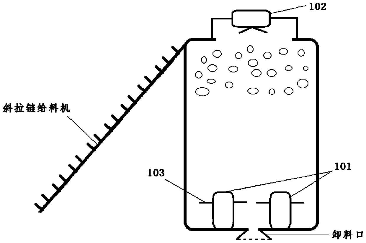
[0038] Depend on figure 1 As shown, a bottom device of a cement silo includes: a bottom unit 101, a material level unit 102, and a control unit; it also includes multiple sets of high-pressure springs;

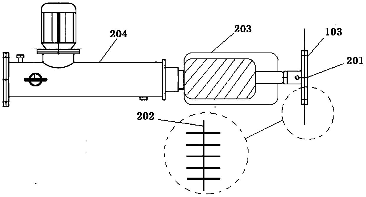
[0039] Further, the base unit 101 includes: a support surface structure 201, an accumulator 203, and an electro-hydraulic push rod 204. Around the support surface structure 201, comb structures 202 are symmetrically arranged; the support surface structure 201 The lower surface is fixedly arranged at one end of the accumulator 203, and the other end of the accumulator 203 is connected to the telescopic part of the electro-hydraulic push rod 204, and the tail of the electro-hydraulic push rod 204 is fixedly arranged on the cement library bottom;

[0040] As an example, the supporting surface structure 201 is used to lift the cement powder sur...


PUM


Abstract

The invention relates to a bunker bottom device of a cement bunker. The bunker bottom device comprises a bunker bottom unit, a material level unit and a control unit. The bunker bottom device also comprises a plurality of high pressure springs; the bunker bottom unit comprises a supporting face structure, an energy accumulator and an electric-hydraulic pusher, and comb structures are symmetricallyarranged around the supporting face structure; the lower surface of the supporting face structure is fixedly arranged at one end of the energy accumulator while the other end of the energy accumulator is connected to a telescopic part of the electric-hydraulic pusher, and a cement bunker bottom is fixedly arranged at the tail part of the electric-hydraulic pusher. The bunker bottom device is verylow in power consumption, and the cement unit cost is lowered while the bunker bottom device is energy-saving and consumption-reducing; the bunker bottom device is low in noise which is nearly zero,so that the social disputes and the damage to the bodies of workers are reduced; no flying dust is available, leakage and venting of cement powder faces are reduce, and the demand on a matched dust collecting system is reduced; the cement hardening-preventing effect is excellent, and the hardening-preventing effect of cement on the upper part of the cement bunker can be further enhanced by a lifting way.

Description

technical field [0001] The invention belongs to the technical field of storage equipment, in particular to a cement storage bottom device. Background technique [0002] The cement agglomeration in the cement silo is the main factor for the blockage of the cement silo and the reduction of the effective inventory. After the cement agglomerates, more manpower and material resources must be invested to manually remove the walls and bottom of the silo. This maintenance operation is very dangerous. The cement Consolidation is a long-term problem that has plagued cement companies in safe production; especially during the rainy season in the southern region, many construction projects are affected, cement sales are limited, and the inventory is often at a high level. It is difficult to clear the warehouse regularly, and the air is humid. The inner cement is easy to form walls and is thick and hard. If it is not handled properly, personal safety accidents may occur; [0003] At pres...

Claims


Application Information

Patent Timeline
Patent Type & Authority Patents(China)
IPC IPC(8): B28C5/48B28C7/02
CPCB28C5/48B28C7/02
Inventor 林媚张利建苟雪
Owner BINZHOU POLYTECHNIC
Why Eureka
Try Eureka